
Related Manuals for Trinamic TMCM-310


Summary of Contents for Trinamic TMCM-310
- Page 1 TMCM-310 TMCL Firmware Manual Version: 1.02 2011-JAN-11 Trinamic Motion Control GmbH & Co KG Sternstraße 67 D - 20 357 Hamburg, Germany http://www.trinamic.com...
-
Page 2: Table Of Contents
6.7.27 CCO (capture coordinate) ........................... 66 6.7.28 CALCX (calculate using the X register) ....................67 6.7.29 AAP (accumulator to axis parameter) ....................68 6.7.30 AGP (accumulator to global parameter) ....................71 Copyright © 2011, TRINAMIC Motion Control GmbH & Co. KG... - Page 3 Reference search ..............................90 Stall detection ..............................91 Fixing microstep errors ............................ 91 10 Revision history ................................92 10.1 Firmware revision .............................. 92 10.2 Document revision ............................92 11 References..................................93 Copyright © 2011, TRINAMIC Motion Control GmbH & Co. KG...
-
Page 4: Life Support Policy
Specifications are subject to change without notice. Copyright © 2011, TRINAMIC Motion Control GmbH & Co. KG... -
Page 5: Features
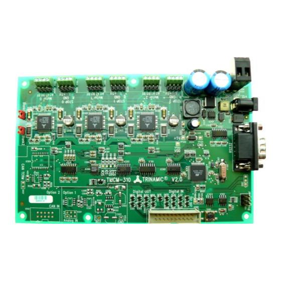
TMCM-310 TMCL™ Firmware Manual (V1.02/2011-JAN-11) 2 Features The TMCM-310 is a triple axis 2-phase stepper motor controller and driver module. It provides a complete single board motion control solution at low cost. Using the integrated additional I/Os it even can do complete system control applications. -
Page 6: Order Codes
QMot stepper motor 42mm, 1A, 0.27Nm 42.3 x 42.3 x 33,5 QSH4218-41-10-035 QMot stepper motor 42mm, 1A, 0.35Nm 42.3 x 42.3 x 38 QSH4218-51-10-049 QMot stepper motor 42mm, 1A, 0.49Nm 42.3 x 42.3 x 47 Copyright © 2011, TRINAMIC Motion Control GmbH & Co. KG... -
Page 7: Overview
TMCM-310 TMCL™ Firmware Manual (V1.02/2011-JAN-11) 4 Overview As with most TRINAMIC modules the software running on the microprocessor of the TMCM-310 consists of two parts, a boot loader and the firmware itself. Whereas the boot loader is installed during production and testing at TRINAMIC and remains –... -
Page 8: Putting The Tmcm-310 Into Operation
5.1 Starting up Connect the motors The TMCM-310 controls up to three 2-phase stepper motors. The screw terminals for the motors are marked on the board with Motor 0, Motor 1 and Motor 2 (2.54mm pitch connectors). Additionally there are electrically identical 4-pin connectors (2.54mm pitch) for motor and stop switches. Connect one coil of the motor to the terminals marked with A0 and A1 and the other coil to the terminals marked with B0 and B1. - Page 9 Connect the power supply: There are two possibilities for connecting the power supply: The power supply can either be connected to the X504/X505 TRINAMIC standard 5.08mm power plug or to the power socket X503 (industry standard power socket with 2.0mm pin diameter). Both connections are electrically identical.
- Page 10 TMCM-310 TMCL™ Firmware Manual (V1.02/2011-JAN-11) Choose COM port and type with the parameters shown below (baud rate 9600 for RS232). Click OK. Copyright © 2011, TRINAMIC Motion Control GmbH & Co. KG...
-
Page 11: Testing With A Simple Tmcl
Download Click on Icon Assemble to convert the TMCL™ into machine code. Then download the program to the TMCM-310 module via the icon Download. Press icon Run. The desired program will be executed. Click Stop button to stop the program. -
Page 12: Operating The Module In Direct Mode
Start TMCL™ Direct Mode. Direct Mode If the communication is established the TMCM-310 is automatically detected. If the module is not detected, please check all points above (cables, interface, power supply, COM port, baud rate). Issue a command by choosing instruction, type (if necessary), motor, and value and click Execute to send it to the module. -
Page 13: Tmcl™ And Tmcl-Ide
Every motion control command can be given by a host computer or can be stored in an EEPROM on the TMCM-310 to form programs that run stand-alone on the module. For this purpose there are not only motion control commands but also commands to control the program structure (like conditional jumps, compare and calculating). -
Page 14: Reply Format
The checksum is also calculated by adding up all the other bytes using an 8-bit addition. When using CAN bus, the first byte (reply address) and the last byte (checksum) are left out. Do not send the next command before you have received the reply! Copyright © 2011, TRINAMIC Motion Control GmbH & Co. KG... -
Page 15: Status Codes
These commands control the motion of the motor. They are the most important commands and can be used in direct mode or in stand-alone mode. Command Mnemonic Meaning number Rotate left Rotate right Move to position Motor stop Reference search Store coordinate Capture coordinate Get coordinate Copyright © 2011, TRINAMIC Motion Control GmbH & Co. KG... -
Page 16: Parameter Commands
Jump conditional COMP Compare accumulator with constant value Clear error flags CSUB Call subroutine RSUB Return from subroutine WAIT Wait for a specified event STOP End of a TMCL™ program Copyright © 2011, TRINAMIC Motion Control GmbH & Co. KG... -
Page 17: Calculation Commands
GAP, GGP or GIO to the module (e.g. to query the actual position of the motor) without affecting the flow of the TMCL™ program running on the module. Copyright © 2011, TRINAMIC Motion Control GmbH & Co. KG... -
Page 18: Tmcl™ List Of Commands
<condition>, <motor number>, Wait with further program execution <ticks> STOP Stop program execution <bus number>, <number of SPI bus access bites>, <send data> <coordinate number>, <motor Set coordinate number>, <position> Copyright © 2011, TRINAMIC Motion Control GmbH & Co. KG... - Page 19 This command does not send back a reply. 138 – reserved 139 – enter ASCII Enter ASCII command line (see (don’t care) (don’t care) (don’t care) mode chapter 6.6) Copyright © 2011, TRINAMIC Motion Control GmbH & Co. KG...
-
Page 20: The Ascii Interface
Bit 5 determine how the characters that are entered are echoed back. Normally, both bits are set to zero. In this case every character that is entered is echoed back when the module is addressed. Character can also Copyright © 2011, TRINAMIC Motion Control GmbH & Co. KG... - Page 21 <CR> character has been sent. When bit 5 is set and bit 4 is clear there will be no echo, only the reply will be sent. Copyright © 2011, TRINAMIC Motion Control GmbH & Co. KG...
-
Page 22: Commands
Rotate right, motor #2, velocity = 350 Mnemonic: ROR 2, 350 Binary: Byte Index Function Target- Instruction Type Motor/ Operand Operand Operand Operand Checksum address Number Bank Byte3 Byte2 Byte1 Byte0 Value (hex) Copyright © 2011, TRINAMIC Motion Control GmbH & Co. KG... -
Page 23: Rol (Rotate Left)
Rotate left, motor #1, velocity = 1200 Mnemonic: ROL 1, 1200 Binary: Byte Index Function Target- Instruction Type Motor/ Operand Operand Operand Operand Checksum address Number Bank Byte3 Byte2 Byte1 Byte0 Value (hex) Copyright © 2011, TRINAMIC Motion Control GmbH & Co. KG... -
Page 24: Mst (Motor Stop)
(don't care) Example: Stop motor #1 Mnemonic: MST 1 Binary: Byte Index Function Target- Instruction Type Motor/ Operand Operand Operand Operand Checksum address Number Bank Byte3 Byte2 Byte1 Byte0 Value (hex) Copyright © 2011, TRINAMIC Motion Control GmbH & Co. KG... -
Page 25: Mvp (Move To Position)
Move motor #1 to (absolute) position 90000 Mnemonic: MVP ABS, 1, 9000 Binary: Byte Index Function Target- Instruction Type Motor/ Operand Operand Operand Operand Checksum address Number Bank Byte3 Byte2 Byte1 Byte0 Value (hex) Copyright © 2011, TRINAMIC Motion Control GmbH & Co. KG... - Page 26 It is possible to use stall detection. Please see section 9.2 for details. When moving to a coordinate, the coordinate has to be set properly in advance with the help of the SCO command (see 6.7.25). Copyright © 2011, TRINAMIC Motion Control GmbH & Co. KG...
-
Page 27: Sap (Set Axis Parameter)
The most important motor setting, since too 0… 1500 current high values might cause motor damage! The [mA] maximum value is 1500 (which mean 100% of the maximum current of the module). Copyright © 2011, TRINAMIC Motion Control GmbH & Co. KG... - Page 28 (in steps of one). pulse divisor The exponent of the scaling factor for the 0…13 pulse (step) generator – should de/incremented carefully (in steps of one). Copyright © 2011, TRINAMIC Motion Control GmbH & Co. KG...
- Page 29 200 (value equates 2000msec). Please use the TMCL-IDE axis parameter calculation tool for getting best values. Example: Set the absolute maximum current of motor #1 to 200mA Mnemonic: SAP 6, 1, 200 Binary: Copyright © 2011, TRINAMIC Motion Control GmbH & Co. KG...
- Page 30 TMCM-310 TMCL™ Firmware Manual (V1.02/2011-JAN-11) Byte Index Function Target- Instruction Type Motor/ Operand Operand Operand Operand Checksum address Number Bank Byte3 Byte2 Byte1 Byte0 Value (hex) Copyright © 2011, TRINAMIC Motion Control GmbH & Co. KG...
-
Page 31: Gap (Get Axis Parameter)
6.7.6 GAP (get axis parameter) Most parameters of the TMCM-310 can be adjusted individually for the axis. With this parameter they can be read out. In stand-alone mode the requested value is also transferred to the accumulator register for further processing purposes (such as conditioned jumps). - Page 32 The position counter will use the full resolution, but, however, the motor will resolve a maximum of 24 different microsteps only for the 32 or 64 microstep units. Copyright © 2011, TRINAMIC Motion Control GmbH & Co. KG...
- Page 33 Switch off mixed decay to get usable results. actual load value Readout of the actual load value used for stall 0…7 detection. driver error flags TMC236 error flags. Copyright © 2011, TRINAMIC Motion Control GmbH & Co. KG...
- Page 34 Byte2 Byte1 Byte0 Value (hex) Reply: Byte Index Function Host- Target- Status Instruction Operand Operand Operand Operand Checksum address address Byte3 Byte2 Byte1 Byte0 Value (hex) status=no error, position=711 Copyright © 2011, TRINAMIC Motion Control GmbH & Co. KG...
-
Page 35: Stap (Store Axis Parameter)
Deactivates the stop function of the left disable switch resp. reference switch if set. minimum speed Should always be set 1 to ensure exact reaching of the target position. Do not change! Copyright © 2011, TRINAMIC Motion Control GmbH & Co. KG... - Page 36 3 – Three-switch-mode: the right switch is searched first and afterwards the reference switch will be searched. Please see chapter 6.7.13 for details on reference search. Copyright © 2011, TRINAMIC Motion Control GmbH & Co. KG...
- Page 37 Note: The STAP command will not have any effect when the configuration EEPROM is locked (refer to 8.1). In direct mode, the error code 5 (configuration EEPROM locked, see also section 6.2.1) will be returned in this case. Copyright © 2011, TRINAMIC Motion Control GmbH & Co. KG...
-
Page 38: Rsap (Restore Axis Parameter)
Deactivates the stop function of the left disable switch resp. reference switch if set. minimum speed Should always be set 1 to ensure exact reaching of the target position. Do not change! Copyright © 2011, TRINAMIC Motion Control GmbH & Co. KG... - Page 39 3 – Three-switch-mode: the right switch is searched first and afterwards the reference switch will be searched. Please see chapter 6.7.13 for details on reference search. Copyright © 2011, TRINAMIC Motion Control GmbH & Co. KG...
- Page 40 Restore the maximum current of motor #1 Mnemonic: RSAP 6, 1 Binary: Byte Index Function Target- Instruction Type Motor/ Operand Operand Operand Operand Checksum address Number Bank Byte3 Byte2 Byte1 Byte0 Value (hex) Copyright © 2011, TRINAMIC Motion Control GmbH & Co. KG...
-
Page 41: Sgp (Set Global Parameter)
1 – start up in ASCII mode Bits 4 and 5: 00 – Echo back each character 01 – Echo back complete command 10 – Do not send echo, only send command reply Copyright © 2011, TRINAMIC Motion Control GmbH & Co. KG... - Page 42 The global parameter bank 1 is normally not available. It may be used for customer specific extensions of the firmware. Together with user definable commands (see section 7.3) these variables form the interface between extensions of the firmware (written in C) and TMCL applications. Copyright © 2011, TRINAMIC Motion Control GmbH & Co. KG...
- Page 43 Instruction Type Motor/ Operand Operand Operand Operand Checksum address Number Bank Byte3 Byte2 Byte1 Byte0 Value (hex) Please refer to chapter 8 for more information about bank 0 to 2. Copyright © 2011, TRINAMIC Motion Control GmbH & Co. KG...
-
Page 44: Ggp (Get Global Parameter)
125kBit/s 250kBit/s 500kBit/s 1000kBit/s Default CAN reply ID The CAN ID for replies from the board (default: 2) 0…7ff CAN ID The module (target) address for CAN (default: 1) 0…7ff Copyright © 2011, TRINAMIC Motion Control GmbH & Co. KG... - Page 45 The global parameter bank 1 is normally not available. It may be used for customer specific extensions of the firmware. Together with user definable commands (see section 7.3) these variables form the interface between extensions of the firmware (written in C) and TMCL applications. Copyright © 2011, TRINAMIC Motion Control GmbH & Co. KG...
- Page 46 Operand Operand Operand Operand Checksum address address Byte3 Byte2 Byte1 Byte0 Value (hex) Status=no error, Value=1 Please refer to chapter 8 for more information about bank 0 to 2. Copyright © 2011, TRINAMIC Motion Control GmbH & Co. KG...
-
Page 47: Stgp (Store Global Parameter)
TMCL™ applications general purpose variable #17 for use in TMCL™ applications general purpose variable #18 for use in TMCL™ applications general purpose variable #19 for use in TMCL™ applications Copyright © 2011, TRINAMIC Motion Control GmbH & Co. KG... - Page 48 8.1). In direct mode, the error code 5 (configuration EEPROM locked, see also section 6.2.1) will be returned in this case. Please refer to chapter 8 for more information about bank 0 to 2. Copyright © 2011, TRINAMIC Motion Control GmbH & Co. KG...
-
Page 49: Rsgp (Restore Global Parameter)
TMCL™ applications general purpose variable #15 for use in TMCL™ applications general purpose variable #16 for use in TMCL™ applications general purpose variable #17 for use in TMCL™ applications Copyright © 2011, TRINAMIC Motion Control GmbH & Co. KG... - Page 50 Instruction Type Motor/ Operand Operand Operand Operand Checksum address Number Bank Byte3 Byte2 Byte1 Byte0 Value (hex) Please refer to chapter 8 for more information about bank 0 to 2. Copyright © 2011, TRINAMIC Motion Control GmbH & Co. KG...
-
Page 51: Rfs (Reference Search)
TMCM-310 TMCL™ Firmware Manual (V1.02/2011-JAN-11) 6.7.13 RFS (reference search) The TMCM-310 module has a built-in reference search algorithm which can be used. The reference search algorithm provides switching point calibration and three switch modes. The status of the reference search can also be queried to see if it has already finished. -
Page 52: Sio (Set Output)
Mnemonic: SIO 255, 2, 255 The following program will show the states of the eight input lines on the output lines: Loop: GIO 255, 0 SIO 255, 2,-1 JA Loop Copyright © 2011, TRINAMIC Motion Control GmbH & Co. KG... -
Page 53: Gio (Get Input/Output)
GIO 0, 0 IN_1 GIO 1, 0 IN_2 GIO 2, 0 IN_3 GIO 3, 0 IN_4 GIO 4, 0 IN_5 GIO 5, 0 IN_6 GIO 6, 0 IN_7 GIO 7, 0 Copyright © 2011, TRINAMIC Motion Control GmbH & Co. KG... - Page 54 OUT_2 GIO 2, 2, <n> OUT_3 GIO 3, 2, <n> OUT_4 GIO 4, 2, <n> OUT_5 GIO 5, 2, <n> OUT_6 GIO 6, 2, <n> OUT_7 GIO 7, 2, <n> Copyright © 2011, TRINAMIC Motion Control GmbH & Co. KG...
-
Page 55: Calc (Calculate)
Multiply accu by -5000 Mnemonic: CALC MUL, -5000 Binary: Byte Index Function Target- Instruction Type Motor/ Operand Operand Operand Operand Checksum address Number Bank Byte3 Byte2 Byte1 Byte0 Value (hex) Copyright © 2011, TRINAMIC Motion Control GmbH & Co. KG... -
Page 56: Comp (Compare)
//jump, type: 5 greater/equal, the label must be defined somewhere else in the program Binary format of the COMP 1000 command: Byte Index Function Target- Instruction Type Motor/ Operand Operand Operand Operand Checksum address Number Bank Byte3 Byte2 Byte1 Byte0 Value (hex) Copyright © 2011, TRINAMIC Motion Control GmbH & Co. KG... -
Page 57: Jc (Jump Conditional)
Binary format of “JC GE, Label” when Label is at address 10: Byte Index Function Target- Instruction Type Motor/ Operand Operand Operand Operand Checksum address Number Bank Byte3 Byte2 Byte1 Byte0 Value (hex) Copyright © 2011, TRINAMIC Motion Control GmbH & Co. KG... -
Page 58: Ja (Jump Always)
Binary format of “JA Loop” assuming that the label “Loop” is at address 20: Byte Index Function Target- Instruction Type Motor/ Operand Operand Operand Operand Checksum address Number Bank Byte3 Byte2 Byte1 Byte0 Value (hex) Copyright © 2011, TRINAMIC Motion Control GmbH & Co. KG... -
Page 59: Csub (Call Subroutine)
Binary format of the “CSUB SubW” command assuming that the label “SubW” is at address 100: Byte Index Function Target- Instruction Type Motor/ Operand Operand Operand Operand Checksum address Number Bank Byte3 Byte2 Byte1 Byte0 Value (hex) Copyright © 2011, TRINAMIC Motion Control GmbH & Co. KG... -
Page 60: Rsub (Return From Subroutine)
Example: Please have a look at the CSUB example below. Binary format of RSUB: Byte Index Function Target- Instruction Type Motor/ Operand Operand Operand Operand Checksum address Number Bank Byte3 Byte2 Byte1 Byte0 Value (hex) Copyright © 2011, TRINAMIC Motion Control GmbH & Co. KG... -
Page 61: Wait (Wait For An Event To Occur)
Wait for motor #1 to reach its target position, without timeout Mnemonic: WAIT POS, 1, 0 Binary: Byte Index Function Target- Instruction Type Motor/ Operand Operand Operand Operand Checksum address Number Bank Byte3 Byte2 Byte1 Byte0 Value (hex) Copyright © 2011, TRINAMIC Motion Control GmbH & Co. KG... -
Page 62: Stop (Stop Tmcl™ Program Execution)
(don't care) (don't care) (don't care) Example: Mnemonic: STOP Binary: Byte Index Function Target- Instruction Type Motor/ Operand Operand Operand Operand Checksum address Number Bank Byte3 Byte2 Byte1 Byte0 Value (hex) Copyright © 2011, TRINAMIC Motion Control GmbH & Co. KG... -
Page 63: Sac - Spi Bus Access
SPI_SEL0, output contents of accumulator Do not use SPI_SLE1, output contents of accumulator SPI_SEL2, output contents of accumulator Please note the gap in the bus numbers; do not use 1 or 129! Copyright © 2011, TRINAMIC Motion Control GmbH & Co. KG... -
Page 64: Sco (Set Coordinate)
Set coordinate #1 of motor #2 to 1000 Mnemonic: SCO 1, 2, 1000 Binary: Byte Index Function Target- Instruction Type Motor/ Operand Operand Operand Operand Checksum address Number Bank Byte3 Byte2 Byte1 Byte0 Value (hex) Copyright © 2011, TRINAMIC Motion Control GmbH & Co. KG... -
Page 65: Gco (Get Coordinate)
Byte3 Byte2 Byte1 Byte0 Value (hex) Reply: Byte Index Function Target- Target- Status Instruction Operand Operand Operand Operand Checksum address address Byte3 Byte2 Byte1 Byte0 Value (hex) Value: 0 Copyright © 2011, TRINAMIC Motion Control GmbH & Co. KG... -
Page 66: Cco (Capture Coordinate)
Store current position of all axes to coordinate 3 Mnemonic: CCO 3, 7 Binary: Byte Index Function Target- Instruction Type Motor/ Operand Operand Operand Operand Checksum address Number Bank Byte3 Byte2 Byte1 Byte0 Value (hex) Copyright © 2011, TRINAMIC Motion Control GmbH & Co. KG... -
Page 67: Calcx (Calculate Using The X Register)
Example: Multiply accu by X-register Mnemonic: CALCX MUL Binary: Byte Index Function Target- Instruction Type Motor/ Operand Operand Operand Operand Checksum address Number Bank Byte3 Byte2 Byte1 Byte0 Value (hex) Copyright © 2011, TRINAMIC Motion Control GmbH & Co. KG... -
Page 68: Aap (Accumulator To Axis Parameter)
Deactivates the stop function of the left disable switch resp. reference switch if set. minimum speed Should always be set 1 to ensure exact reaching of the target position. Do not change! Copyright © 2011, TRINAMIC Motion Control GmbH & Co. KG... - Page 69 3 – Three-switch-mode: the right switch is searched first and afterwards the reference switch will be searched. Please see chapter 6.7.13 for details on reference search. Copyright © 2011, TRINAMIC Motion Control GmbH & Co. KG...
- Page 70 // jump back to start Binary format of the AAP 0,0 command: Byte Index Function Target- Instruction Type Motor/ Operand Operand Operand Operand Checksum address Number Bank Byte3 Byte2 Byte1 Byte0 Value (hex) Copyright © 2011, TRINAMIC Motion Control GmbH & Co. KG...
-
Page 71: Agp (Accumulator To Global Parameter)
The CAN ID for replies from the board (default: 2) CAN ID The module (target) address for CAN (default: 1) configuration EEPROM Write: 1234 to lock the EEPROM, 4321 to unlock it. lock flag Read: 1=EEPROM locked, 0=EEPROM unlocked. Copyright © 2011, TRINAMIC Motion Control GmbH & Co. KG... - Page 72 1 – coordinates are always stored in the EEPROM only tick timer A 32 bit counter that gets incremented by one every millisecond. It can also be reset to any start value. Copyright © 2011, TRINAMIC Motion Control GmbH & Co. KG...
- Page 73 The global parameter bank 1 is normally not available. It may be used for customer specific extensions of the firmware. Together with user definable commands (see section 7.3) these variables form the interface between extensions of the firmware (written in C) and TMCL applications. Copyright © 2011, TRINAMIC Motion Control GmbH & Co. KG...
- Page 74 Copy accumulator to TMCL™ user variable #3 Mnemonic: AGP 3, 2 Binary: Byte Index Function Target- Instruction Type Motor/ Operand Operand Operand Operand Checksum address Number Bank Byte3 Byte2 Byte1 Byte0 Value (hex) Copyright © 2011, TRINAMIC Motion Control GmbH & Co. KG...
-
Page 75: Cle (Clear Error Flags)
Example: Reset the timeout flag Mnemonic: CLE ETO Binary: Byte Index Function Target- Instruction Type Motor/ Operand Operand Operand Operand Checksum address Number Bank Byte3 Byte2 Byte1 Byte0 Value (hex) Copyright © 2011, TRINAMIC Motion Control GmbH & Co. KG... -
Page 76: Customer Specific Tmcl™ Command Extension (Uf0
The user definable functions UF0…UF7 are predefined, functions without topic for user specific purposes. Contact TRINAMIC for customer specific programming of these functions. Internal function: Call user specific functions implemented in C by TRINAMIC. Related commands: none Mnemonic: UF0...UF7 Binary representation: INSTRUCTION NO. -
Page 77: Request Target Position Reached Event
Additional reply in direct mode (after motors have reached their target positions): Byte Index Function Target- Target- Status Instruction Operand Operand Operand Operand Checksum address address Byte3 Byte2 Byte1 Byte0 Value (hex) Motor bit <checksum mask > Copyright © 2011, TRINAMIC Motion Control GmbH & Co. KG... -
Page 78: Bin (Return To Binary Mode)
This command can only be used in ASCII mode. It quits the ASCII mode and returns to binary mode. Related Commands: none Mnemonic: BIN Binary representation: This command does not have a binary representation as it can only be used in ASCII mode. Copyright © 2011, TRINAMIC Motion Control GmbH & Co. KG... -
Page 79: Tmcl™ Control Functions
This command does not send back a reply. 138 – reserved 139 – enter ASCII Enter ASCII command line (see (don’t care) (don’t care) (don’t care) mode chapter 6.6) Copyright © 2011, TRINAMIC Motion Control GmbH & Co. KG... - Page 80 The version number is output in the value field of the reply in the following way: Byte index in value field Contents Version number, low byte Version number, high byte Type number, low byte (currently not used) Type number, high byte (currently not used) Copyright © 2011, TRINAMIC Motion Control GmbH & Co. KG...
-
Page 81: Axis Parameters
(stop) switch. right limit switch The logical state of the (right) limit switch. status left limit switch The logical state of the left limit switch (in status three switch mode) Copyright © 2011, TRINAMIC Motion Control GmbH & Co. KG... - Page 82 (in steps of one). pulse divisor The exponent of the scaling factor for the 0…13 pulse (step) generator – should de/incremented carefully (in steps of one). Copyright © 2011, TRINAMIC Motion Control GmbH & Co. KG...
- Page 83 Standstill period before the current is changed 1… 65535 delay down to standby current. The standard value [10msec] is 200 (value equates 2000msec). * Unit of acceleration: Copyright © 2011, TRINAMIC Motion Control GmbH & Co. KG...
- Page 84 TMCM-310 TMCL™ Firmware Manual (V1.02/2011-JAN-11) Please use the TMCL-IDE axis parameter calculation tool for getting best values. Copyright © 2011, TRINAMIC Motion Control GmbH & Co. KG...
-
Page 85: Global Parameters
TMCL-IDE and serve for loading micro step and driver tables. Normally these parameters remain untouched. If you want to use them for loading your specific values with your PC software please contact TRINAMIC and ask how to do this. Otherwise you might cause damage on the motor driver! Number Parameter... - Page 86 0 – coordinates are stored in the RAM only (but can be 0 or 1 copied explicitly between RAM and EEPROM) 1 – coordinates are always stored in the EEPROM only Copyright © 2011, TRINAMIC Motion Control GmbH & Co. KG...
- Page 87 A 32 bit counter that gets incremented by one every millisecond. It can also be reset to any start value. Choose a random number. Read only! random number 0…21474 83647 Copyright © 2011, TRINAMIC Motion Control GmbH & Co. KG...
-
Page 88: Bank 1
The global parameter bank 1 is normally not available. It may be used for customer specific extensions of the firmware. Together with user definable commands (see section 7.3) these variables form the interface between extensions of the firmware (written in C) and TMCL applications. Copyright © 2011, TRINAMIC Motion Control GmbH & Co. KG... -
Page 89: Bank 2
#18 for use in TMCL™ applications …+2 general purpose variable #19 for use in TMCL™ applications …+2 20..55 general purpose variables for use in TMCL™ applications …+2 #20..#55 Copyright © 2011, TRINAMIC Motion Control GmbH & Co. KG... -
Page 90: Hints And Tips
Figure 9.1: Two limit switches Figure 9.2: Limit switches with extra Figure 9.3: Circular reference switch system Copyright © 2011, TRINAMIC Motion Control GmbH & Co. KG... -
Page 91: Stall Detection
TMCM-310 TMCL™ Firmware Manual (V1.02/2011-JAN-11) 9.2 Stall detection The TMCM-310 is offered with the stallGuard™ option. In this case the module is equipped with three TMC246 motor driver chips, which feature load measurement that can be used for stall detection. Stall detection means that the motor will be stopped when the load gets too high. -
Page 92: Revision History
Most recent version 10.2 Document revision Version Date Author Description 1.00 2009-OKT-15 Initial version 1.01 2009-OKT-27 Axis parameters 194 and 195 corrected 1.02 2011-JAN-11 Value range of axis parameter 6 corrected. Copyright © 2011, TRINAMIC Motion Control GmbH & Co. KG... -
Page 93: References
TMCM-310 TMCL™ Firmware Manual (V1.02/2011-JAN-11) 11 References [TMCL] TMCL™ reference and programming manual (see http://www.trinamic.com) [TMCM-310] TMCM-310 Hardware Manual (see http://www.trinamic.com) Copyright © 2011, TRINAMIC Motion Control GmbH & Co. KG...
Need help?
Do you have a question about the TMCM-310 and is the answer not in the manual?
Questions and answers