Table of Contents
Advertisement
Quick Links
TMCM-302
3 - Axis Stepper Motor Motion Control Module
for Step / Direction drivers
Manual
Version: 1.12
th
December 6
, 2006
Trinamic Motion Control GmbH & Co. KG
Sternstraße 67
D – 20357 Hamburg, Germany
Phone +49-40-51 48 06 – 0
FAX: +49-40-51 48 06 – 60
http://www.trinamic.com
Copyright © 2006, TRINAMIC Motion Control GmbH & Co. KG
Advertisement
Table of Contents

Related Manuals for Trinamic TMCM-302


Summary of Contents for Trinamic TMCM-302
- Page 1 December 6 , 2006 Trinamic Motion Control GmbH & Co. KG Sternstraße 67 D – 20357 Hamburg, Germany Phone +49-40-51 48 06 – 0 FAX: +49-40-51 48 06 – 60 http://www.trinamic.com Copyright © 2006, TRINAMIC Motion Control GmbH & Co. KG...
-
Page 2: Table Of Contents
RS-232.............................10 5.3.3 RS-485.............................11 Step-/Direction output........................12 Connecting the drivers........................12 5.5.1 Connecting the TMCM-302 to a power driver module with Step/Direction-Interface ....12 5.5.2 Connecting the TMCM-302 to drivers with an SPI-Interface ...........15 Ramp Profiles ...........................17 Reference switches ..........................18 5.7.1 Left and right limit switches......................18 5.7.2... - Page 3 List of Figures Figure 3.1: Dimensions..........................6 Figure 3.2: Pin order of the connector..................... 7 Figure 5.1: Main parts of the TMCM-302 ....................8 Figure 5.2: Connecting CAN........................10 Figure 5.3: Connecting RS-232......................11 Figure 5.4: Connecting the RS-485 interface ..................11 Figure 5.5: Step-/Direction output signals .....................
-
Page 4: Features
4/23 1 Features The TMCM-302 is a triple axis stepper motor controller module for external power drivers with step / direction interface. With its very small size it is dedicated to embedded applications, where centralized or de-centralized high power drivers are desired. The board can be connected to a baseboard or customized electronics with a pin connector. -
Page 5: Life Support Policy
Specifications subject to change without notice. Copyright © 2006, TRINAMIC Motion Control GmbH & Co. KG... -
Page 6: Electrical And Mechanical Interfacing
Note : all dimensions in mm Figure 3.1: Dimensions The size of the module 80x50mm, the same as of the other Trinamic motion control modules. It also uses the same connector. Copyright © 2006, TRINAMIC Motion Control GmbH & Co. KG... -
Page 7: Connecting The Module
Reserved SPI_M1_OUT RS-485 Direction STEP_M0 InOut CAN - SPI_M1_CLK RS-232 RxD DIR_M0 InOut CAN + SPI_M2_OUT RS-232 TxD Table 3.1: Pinout 68-Pin Connector Figure 3.2: Pin order of the connector Copyright © 2006, TRINAMIC Motion Control GmbH & Co. KG... -
Page 8: Operational Ratings
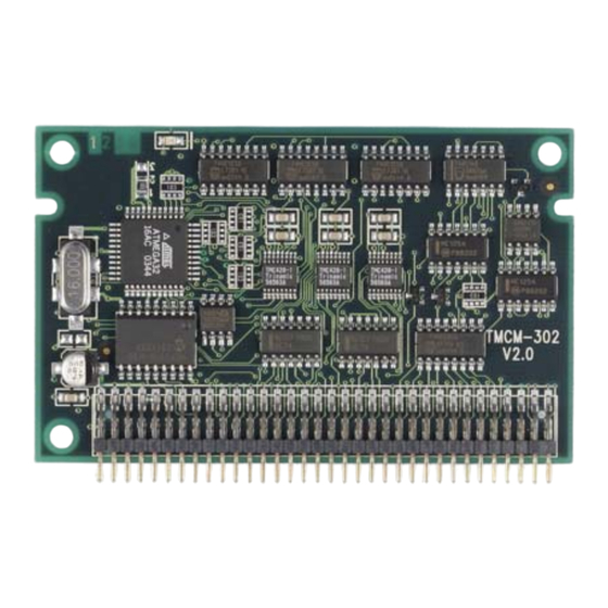
Table 4.1: Operational Ratings 5 Functional Description In Figure 5.1 the main parts oft the TMCM-302 module are shown. The module mainly consists of three TMC428 motion controller, the TMCL program memory (EEPROM) and the host interfaces (RS- 232, RS-485 and CAN). -
Page 9: System Architecture
SPI-Interface can be added, but this module is mainly intended for use with Step/Direction drivers. 5.2 Power Supply The power supply for the TMCM-302 is +5VDC for module functionality. Please use all listed pins for the power supply inputs and ground parallel. Refer to 6 Putting the TMCM-302 into Operation. Function... -
Page 10: Host Communication
2, 4, 6, 8, 10 Connect to ground Table 5.3: Pinout for RS-232 Connection Note: The RS-232 must be operated with TTL-Levels (0V, 5V), since there is no level shifter onboard! Copyright © 2006, TRINAMIC Motion Control GmbH & Co. KG... -
Page 11: Figure 5.3: Connecting Rs-232
1: Driver enable RS-485 Receive Data RS-485 Transmit Data 2, 4, 6, 8, 10 Connect to ground Table 5.4: Pinout for RS-485 Connection Note: The TMCM-302 Module does not contain any RS-485 transceivers! 68-Pin-Connector TMCM-302 Transceiver, Transceiver, HOST e.g. MAX485 e.g. -
Page 12: Step-/Direction Output
12/23 5.4 Step-/Direction output The TMCM-302 generates step- and direction output signals, which are pre-conditioned in order to directly be connected to microstep driver units with 5V inputs. See Figure 5.5 for the output timing. Some driver units might require inverters / level shifters in order to adapt step polarity and voltage. -
Page 13: Figure 5.6: Application Environment Using The Step/Direction-Interface
Motor 0 Motor 1 Motor 2 Figure 5.6: Application Environment using the Step/Direction-Interface Examples: Connection of the TMCM-302 with the Monopack2 (power driver module with a Step/Direction-Interface), TMCM-023 or TMCM-013. TMCM-302 Power module with Step/ Pin 68 Direction-Interface, e.g. -
Page 14: Figure 5.8: Application With Tmcm-023 With 3 Step/Direction-Interfaces
Pin 36 STEP_M1 Pin 34 DIR_M0 Pin 32 STEP_M0 Pin 6 Pin 4 Pin 2 +5V DC VS = 7...28V Motor connection Figure 5.9: Application with TMCM-013 with a Step/Direction-Interface Copyright © 2006, TRINAMIC Motion Control GmbH & Co. KG... -
Page 15: Connecting The Tmcm-302 To Drivers With An Spi-Interface
TMCM-302 Manual V1.12 15/23 5.5.2 Connecting the TMCM-302 to drivers with an SPI-Interface The pins connecting the TMCM-302 with the Add-On-Board using the SPI-Interface are listed in Table 5.6. Pin Number Direction Name Limits Description nSCS0 Chip Select for Driver 0... -
Page 16: Figure 5.11: Application With An Spi-Stepper Motor Driver
Pin 26 OUTB1 Pin 24 OUTB2 Pin 22 Pin 20 Pin 2 TMC236 GND: Pin 2, 4, 6, 8 : Pin 1, 3 Figure 5.11: Application with an SPI-stepper motor driver Copyright © 2006, TRINAMIC Motion Control GmbH & Co. KG... -
Page 17: Ramp Profiles
TMCM-302 Manual V1.12 17/23 5.6 Ramp Profiles The speed profile is automatically worked out by the TMCM-302 from the values for the minimum speed, maximum speed and acceleration specified by the user with the TMCL. Two modes of operation for the course of velocity are available for selection. -
Page 18: Reference Switches
Note: The TMCM-302 does not contain any pullup resistors for the reference switches! 5.7.1 Left and right limit switches The TMCM-302 can be configured so that a motor has a left and a right limit switch (Figure 5.14). The motor stops when the traveler has reached one of the limit switches. -
Page 19: One Limit Switch For Circular Systems
Port expansion Pin 3, output Out_4 Port expansion Pin 4, output Out_5 Port expansion Pin 5, output Out_6 Port expansion Pin 6, output Out_7 Port expansion Pin 7, output Table 5.9: Pinout port expansion Copyright © 2006, TRINAMIC Motion Control GmbH & Co. KG... -
Page 20: Miscellaneous Connections
Table 5.10: Miscellaneous Connections 6 Putting the TMCM-302 into Operation On the basis of a small example it is shown step by step how the TMCM-302 is set into operation. Experienced users could skip this chapter and proceed to chapter 6: Example: The following application is to implement with the TMCL-IDE Software development environment in the TMCM-302 module. -
Page 21: Tmcm-302 Operational Description
Press Icon “Run”. The desired program will be executed. A documentation about the TMCL operations can be found in “TMCL Reference and Programming Manual”. The next chapter discusses additional operations to turn the TMCM-302 into a high performance motion control system. -
Page 22: Tmcl
8 TMCL TMCL, the TRINAMIC Motion Control Language, is described in a separate documentation, the TMCL Reference and Programming Manual. This manual is provided on the TMC TechLib CD and on the web site of TRINAMIC: www.trinamic.com. Please refer to these sources for updated data sheets and application notes. -
Page 23: Revision History
Step-/Dir applications corrected Table 9.1: Documentation Revisions 9.2 Firmware Revision Version Comment Description 3.24 Initial Release Please refer to TMCL documentation Table 9.2: Firmware Revisions 10 References [TMCL] TMCL manual (see http://www.trinamic.com) Copyright © 2006, TRINAMIC Motion Control GmbH & Co. KG...
Need help?
Do you have a question about the TMCM-302 and is the answer not in the manual?
Questions and answers