Table of Contents
Advertisement
®
®
Stryker
and Neptune
are trademarks and/or registered trademarks of the Stryker Corporation.
2014/12
Print Date: Dec 16, 2014 04:03:57 PM
0000026959, Rev. C Effective Date: Dec 16, 2014 3:43:21 PM
Waste Management System
Service and Installation Manual
Domestic/ International
0702-002-619 Rev C
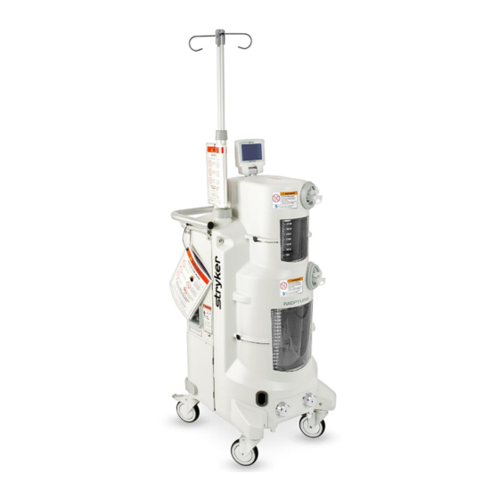
Neptune
120V/230V ROVER - ULTRA
REF 0702-001-000
0702-002-000
120V/230V DOCKING STATION
REF 0702-014-000
0702-015-000
www.stryker.com
®
2
Advertisement
Table of Contents
Troubleshooting


Need help?
Do you have a question about the Neptune 2 ROVER ULTRA and is the answer not in the manual?
Questions and answers