Stryker Neptune 2 Instructions For Use Manual
Waste management system
Hide thumbs
Also See for Neptune 2:
- Instructions for use manual (71 pages) ,
- Service and installation manual (233 pages) ,
- Installation, operation and maintenance manual (24 pages)
Advertisement
Table of Contents
- 1 Indications for Use
- 2 Symbol Definitions
- 3 Cleaning Recommendations
- 4 Storage and Handling
- 5 Periodic Maintenance
- 6 Troubleshooting Guide
- 7 Specifications
- 8 Guidance and Manufacturer's Declaration - Electromagnetic Emissions
- 9 Guidance and Manufacturer's Declaration - Electromagnetic Immunity
- Download this manual
Advertisement
Table of Contents

Related Manuals for Stryker Neptune 2


Summary of Contents for Stryker Neptune 2
- Page 2 Waste Management System Site Preparation and Docking Station Installation 120 V Docking Station REF 0702-014-000 230 V Docking Station REF 0702-015-000 Instructions For Use Stryker and Neptune are trademarks and/or registered trademarks of the Stryker Corporation. 2008/04 0702-014-700 Rev-B www.stryker.com...
-
Page 3: Indications For Use
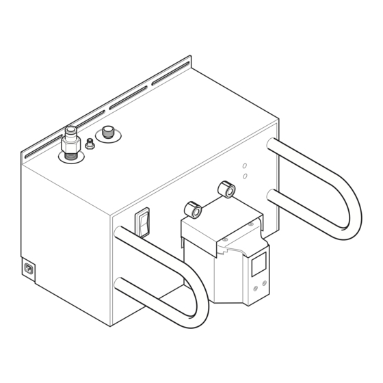
A triangle with an exclamation point alerts the health care professional to read and understand the accompanying • Take special precautions regarding electromagnetic compatibility (EMC) instructions, especially the operating, maintenance, and when using electrical equipment like this system. Install and place this safety information. system into service according to the EMC information contained in this manual. Portable and mobile RF communications equipment can affect the For Use With function of this system. • DO NOT use this equipment in the presence of a mixture consisting of a The Stryker Docking Station (docker) is for use with the Neptune 2 Waste flammable anesthetic and air or oxygen or nitrous oxide. Management System, specifically the Neptune 2 Rover (rover). Indications For Use • Only trained and experienced health care professionals should install and maintain this equipment. The Neptune Waste Management System is intended to be used in the • The Bloodborne Pathogens Standard provided by the United States operating room, pathology, surgical centers, and doctor’s offices to collect Occupational Safety and Health Association (US OSHA) requires all and dispose of surgical fluid waste as well as collect smoke generated from workers with exposure to “potentially infectious materials” wear the correct electrocautery or laser devices. - Page 4 Water Inlet Port - Allows fresh water to enter the rover when the rover is connected to the docker. Ethernet and USB Ports - These ports are located on the side panel (not visible in illustration) and may be accessed by removing a cover. Allows for Stryker-approved software upgrades and maintenance. Power Switch - The toggle switch allows for the application or removal of facility power. Infrared Communication Windows (two) - Allows infrared data transfer between the docker and rover. Data transfer is necessary during the docking procedure. Magnets (two) - Provides for the automatic physical alignment and connection of the rover to the docker.
-
Page 5: Symbol Definitions
2008/04 0702-014-700 Rev-B Instructions Figure 3 Docking Station Installation Symbol Definitions POWER POWER UNIVERSAL ETHERNET PINCH POINT WASTE DETERGENT WATER INLET PORT SERIAL BUS PORT KEEP HANDS OUT OUTLET PORT INLET PORT (USB) PORT www.stryker.com... -
Page 6: Cleaning Recommendations
Specifications section for details. 3. Connect the water inlet hose between the water inlet port of the docker and the facility water supply. WARNING: Follow the current local regulations governing biohazard waste to safely handle and dispose of surgical fluid waste. 4. Connect the waste outlet hose between the waste outlet port of the docker and the drain emptying into the facility waste disposal system. NOTE: A properly connected waste outlet hose will minimize the escape of noxious fumes and odors (see figure 3). 5. Connect the power cord between the electrical receptacle of the docker and the facility electrical power source. 6. Press the power switch ON. Observe the power switch illuminate. NOTE: Before docking the rover, always allow the docker to warm up for at least 60 seconds after applying initial power to the docker. 7. Open the facility water valve to allow water to flow to the docker. Inspect the water supply connections for any leaks. Repair any plumbing to stop leakage if necessary. 8. Connect the detergent inlet tube to the detergent inlet port of the docking station. 9. To connect the detergent, see the label instructions on the Stryker- approved detergent REF 0700-001-026. To Replace the Detergent Bottle 1. Remove the detergent inlet tube from the empty bottle. Follow the current local regulations governing environmental protection to recycle or dispose of the bottle. 2. To connect the detergent, see the label instructions on the Stryker- approved detergent REF 0700-001-026. www.stryker.com... -
Page 7: Troubleshooting Guide
2008/04 0702-014-700 Rev-B Troubleshooting Guide* PROBLEM CAUSE ACTION Power switch does not illuminate in the ON Power cord is not connected securely. Connect the power cord securely. position. Water inlet hose is leaking. Water inlet hose is damaged. Contact Stryker.* Waste outlet hose is leaking. Waste outlet hose is damaged. Contact Stryker.* Sporadic electrical interference is experienced. Electrical noise is present. Turn off all the electrical equipment in the room. Relocate the electrical equipment to maximize the distance between the equipment. Increase spatial distance. Plug equipment into different outlets. *DO NOT service this equipment. If you require service, contact your Stryker sales representative or call Stryker Neptune customer service at 1-800-550-7836. Outside the US, contact your nearest Stryker subsidiary. www.stryker.com... -
Page 8: Specifications
0702-014-700 Rev-B 2008/04 Specifications* Neptune 2 Docking Station Model: REF: 0702-014-000 0702-015-000 Electrical Power Requirements: 120 V ~ , 60 Hz, 3.0 A 230 V ~ , 50 Hz, 3.0 A 15 A receptacle connection 10 A [minimum] receptacle connection Size: 23 inch [58.4 cm] width 16 inch [40.6 cm] height 23 inch [58.4 mm] depth Weight: 95 lbs. [ 43 kg] Class I Equipment Type: Enclosure Protection: IPX0 Ordinary Equipment Infrared Communication Windows: Protective Earth Ground:... -
Page 9: Guidance And Manufacturer's Declaration - Electromagnetic Emissions
2008/04 0702-014-700 Rev-B Specifications Guidance and manufacturer's declaration - electromagnetic emissions The Neptune 2 Dockers, REF 0702-014-000 and REF 0702-015-000, are intended for use in the electromagnetic environment specified below. The customer or the user of the Neptune 2 Docker should assure that it is used in such an environment. Emissions test Compliance Electromagnetic environment - guidance RF emissions Group 1 The Neptune 2 Docker uses RF energy only for its internal function. Therefore, its RF emissions are very low and are not likely to cause any interference in nearby electronic CISPR 11 equipment. RF emissions Class A The Neptune 2 Docker is suitable for use in all establishments other than domestic establishments and those directly connected to the public low-voltage power supply CISPR 11 network that supplies buildings used for domestic purposes. - Page 10 0702-014-700 Rev-B 2008/04 Specifications Guidance and manufacturer's declaration - electromagnetic immunity The Neptune 2 Dockers, REF 0702-014-000 and REF 0702-015-000, are intended for use in the electromagnetic environment specified below. The customer or the user of the Neptune 2 Docker should assure that it is used in such an environment. Immunity test IEC 60601 test level Compliance level Electromagnetic environment - guidance Electrostatic discharge ±6 kV contact ±2, 4, 6 kV contact Floors should be wood, concrete or ceramic tile. If floors are covered with (ESD) synthetic material, the relative humidity should be at least 30%. ±8 kV air ±2, 4, 8 kV air...
- Page 11 2008/04 0702-014-700 Rev-B Specifications Recommended separation distances between portable and mobile RF communications equipment and the Neptune 2 Docker The intended for use in the electromagnetic environment in which radiated RF Neptune 2 Dockers, REF 0702-014-000 and REF 0702-015-000, are disturbances are controlled. The customer or the user of the can help prevent electromagnetic interference by maintaining Neptune 2 Docker a minimum distance between portable and mobile RF communications equipment (transmitters) and the as recommended Neptune 2 Docker below, according to the maximum output power of the communications equipment. Separation distance according to frequency of transmitter Rated maximum output power of transmitter 150 kHz to 80 MHz 80 MHz to 800 MHz 800 MHz to 2.5 GHz 0.01 0.12 0.12 0.23...
- Page 12 0702-014-700 Rev-B 2008/04 www.stryker.com...
- Page 13 Stryker Instruments 4100 E. Milham Kalamazoo, Michigan (USA) 49001 1-269-323-7700 1-800-253-3210 Stryker France ZAC Satolas Green Pusignan Av. de Satolas Green 69881 MEYZIEU Cedex France 2008/04 0702-014-700 Rev-B www.stryker.com...
Need help?
Do you have a question about the Neptune 2 and is the answer not in the manual?
Questions and answers