Table of Contents
Advertisement
Advertisement
Table of Contents

Related Manuals for Stryker Crossfire 2


Summary of Contents for Stryker Crossfire 2
- Page 1 DRAFT Crossfire™ 2 REF 0475100000...
-
Page 3: Table Of Contents
Contents Warnings and Cautions ..............3 Product Description/Intended Use ..........7 Package Contents.................8 Available Accessories................8 The Crossfire 2 Console.................9 The Crossfire 2 Interface..............11 Arthroscopy Mode ................12 Indications for Arthroscopic Use............12 Setup and Device Connections............13 Adjusting User and System Settings.............17 Arthroscopic Shaver Controls...............19 RF Ablation Controls................25 Dual Controls. -
Page 5: Warnings And Cautions
Attempt no internal repairs or adjustments not specifically detailed in this operating manual. Refer any readjustments, modifications, and/or repairs to Stryker Endoscopy or its authorized representatives. Pay close attention to the care and cleaning instructions in this manual. Failure to follow these instructions may result in product damage. - Page 6 Keep all electrosurgical equipment away from flammable materials to avoid combustion. To prevent the risk of fire, DO NOT replace console fuses. If it is suspected that fuses are damaged, return console to Stryker for repair. Prior to Surgery DRAFT The operator of the Crossfire 2 system should be a qualified physician,...
- Page 7 monitoring electrodes are NOT recommended. 12. Smoke generated during electrosurgical procedures may be harmful to surgical personnel. Take appropriate precautions by wearing surgical masks or other means of protection. During Surgery DO NOT use the Crossfire 2 system with non-conductive irrigants (e.g. DRAFT sterile water, air, gas, glycine, etc.).
- Page 8 DO NOT remove the cover of the console as this could cause electric shock and product damage. Attempt no internal repairs or adjustments, unless specified otherwise in this manual. Units requiring repair should be returned to Stryker. Disconnect the Crossfire 2 system from the electrical output when inspecting fuses.
-
Page 9: Product Description/Intended Use
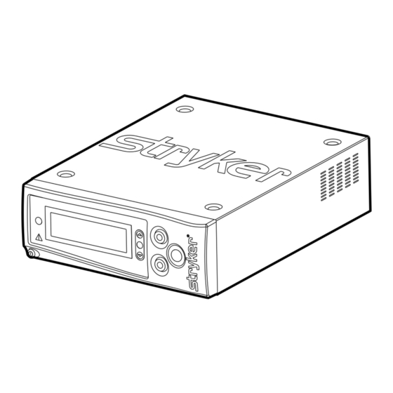
Product Description/Intended Use The Crossfire 2 Integrated Resection and Sealing System is a combination powered shaver system/electrosurgical generator that powers arthroscopic shaver handpieces, RF surgical probes, and vessel-sealing handpieces for use in a variety of arthroscopic, orthopedic, and general laparoscopic surgeries. Illustrated below, the Crossfire 2 system consists of the following components: DRAFT 1. -
Page 10: Package Contents
Package Contents Carefully unpack the Crossfire 2 console and inspect each of the following components. Report any damaged components to Stryker. Crossfire 2 console Hospital-grade power cord User guide DRAFT Available Accessories The Crossfire 2 system is compatible with the following accessories: System Accessories... -
Page 11: The Crossfire 2 Console
The Crossfire 2 Console The Crossfire 2 console is the connection hub for the components of the Crossfire 2 system. It generates RF energy for ablation and vessel sealing, powers motorized shavers, and provides user controls and system feedback. Front Panel The front console panel features ports for connecting handpieces, controls for DRAFT adjusting handpiece settings, and an LCD screen to provide system feedback. - Page 12 Rear Panel The rear panel provides ports for connecting the console to other Stryker equipment. DRAFT 1. Firewire Connectors Enables connection to other Stryker Firewire devices, such as the iSWITCH Universal Wireless Footswitch 2. USB Drive Enables software installation from authorized service personnel 3.
-
Page 13: The Crossfire 2 Interface
The Crossfire 2 Interface The Crossfire 2 interface displays system status, enables you to choose between RF ablation, RF vessel sealing, and shaver modes, and enables you to adjust power and speed settings. Activating the actual handpieces is performed through controls on the handpiece and on the Crossfire Footswitch. -
Page 14: Arthroscopy Mode
Arthroscopy Mode Indications for Arthroscopic Use The Stryker Crossfire 2 system is indicated for use in orthopedic and arthroscopic procedures for the following joints: knee, shoulder, ankle, elbow, wrist, and hip. The crossfire system provides abrasion, resection, debridement DRAFT and removal of bone and soft tissue through its shaver blade; and the ablation and coagulation of soft tissue, as well as hemostasis of blood vessels, through its electrosurgical probe. -
Page 15: Setup And Device Connections
The console and footswitch are not sterile devices and should not enter the sterile field. The Crossfire 2 System is compatible only with the Stryker handpieces and footswitches listed in this manual. Do not connect any equipment not specified in this manual, as unexpected results or serious injury will occur. - Page 16 Place the console on a sturdy platform, such as a Stryker cart. • Select a location according to the recommendations in the preceding EMC tables. • Leave four inches of space around all sides for convection cooling. DRAFT Connect the AC power.
- Page 17 Using the iSWITCH Wireless Footswitch The Crossfire 2 system can be used with the iSWITCH Wireless Footswitch System. DRAFT Connect the Crossfire 2 console to the iSWITCH console using one of the Firewire connection ports on each console. Consult the iSWITCH Operating and Maintenance Manual (P/N 1000- 400-700) for further operation instructions.
- Page 18 Powering the Console On and Off Press the power button to power the console on and off. The button will shine green when the console is on. DRAFT Warning Should emergency shutdown become necessary, power off the console as described above. As an added safety measure, the console can be separated from the AC power mains by detaching the AC power cord from either end.
-
Page 19: Adjusting User And System Settings
User preferences, such as power and cutting speeds and button assignments for the handpiece and footswitch, can be adjusted through the Crossfire 2 interface. Select from the default settings provided with the console, or contact your DRAFT Stryker representative to customize your own. Press DEFAULT SMITH KNEE SMITH SHLDR... - Page 20 System Settings System settings, such as screen brightness, contrast, and system sound can be adjusted through the Crossfire 2 interface. Press and hold (Note: If an RF probe is connected to DRAFT the console, the COAG adjustment screen will appear. Press again to access the system settings screen.) Press...
-
Page 21: Arthroscopic Shaver Controls
Arthroscopic Shaver Controls Warning The Crossfire 2 system is intended for use only by licensed medical professionals, properly trained in the use of electrosurgical equipment and techniques. The Crossfire 2 system generates potentially hazardous levels of energy that can result in injury or even death if improperly used. Before using the Crossfire 2 system in an actual procedure, verify that each DRAFT component is installed and functioning properly. - Page 22 Default Handpiece Controls Default 1 Default 2 / Default 3 None Oscillate Activate / Oscillate (one touch) Deactivate (one touch) TOUCH TOUCH DRAFT Forward Select Mode: (one touch) Oscillate or Forward / TOUCH Reverse Reverse Forward/ Forward (one touch) Reverse (one touch) TOUCH TOUCH...
- Page 23 Default Footswitch Controls The RF and shaver handpieces can also be controlled by the Crossfire Footswitch. The default footswitch controls for the shaver handpiece are shown below. To customize button assignments, contact your Stryker representative. DRAFT Button Function Default 1...
- Page 24 Note: When using small-joint handpieces, only Default 2 settings are available. No other defaults or user preferences can be applied. Adjusting Cutting Speed Use the buttons on the console to manually adjust the power or speed setting for the active handpiece. Note: In shaver mode, the console uses radio frequency identification ( ) to rfid...
- Page 25 Reading the LCD In shaver mode, the LCD will show: 9000 DRAFT MC DISP NAME 1. Footswitch Crossfire Footswitch connected status iSWITCH footswitch connected not connected 2. Footswitch one touch TOUCH response (pressing the foot pedal once will activate the shaver to a default speed;...
- Page 26 System Feedback Event Audible Feedback Visible Feedback (via LCD) Reverse activated five high beeps Forward activated/ low beep resumed DRAFT Adjustments made to one beep for each unit Speed indicator speed settings of change number increases or decreases EN-24...
-
Page 27: Rf Ablation Controls
RF Ablation Controls Warning During use, the RF, Crosseal, and shaver handpieces generate electronic noise that may interfere with EKG readings. Before responding to any erratic EKG readings, first power down the system to ensure the readings are not the result of system noise. DRAFT RF and Crosseal handpieces are intended for single use only and should not be reprocessed or reused. - Page 28 Default footswitch controls The RF and shaver handpieces can also be controlled by the Crossfire Footswitch. The default footswitch controls for the RF probe are shown below. To customize button assignments, contact your Stryker representative. DRAFT Button Function (controls are the same for defaults...
- Page 29 Adjusting CUT power To adjust CUT power: • Press the buttons on the console • Press the gray button on the handpiece (increase) • Press the I (decrease) and III (increase) buttons on the footswitch Adjusting COAG power DRAFT To adjust COAG power: COAG1 Press and hold .
- Page 30 Reading the LCD In RF ablation mode, the LCD will show: DRAFT . . . SERFAS 1. Footswitch status Crossfire Footswitch connected iSwitch footswitch connected not connected 2. Mode cut mode activated coagulation mode activated 3. Force modulation force modulation activated force modulation not activated 4.
- Page 31 System Feedback Event Audible Feedback Visible Feedback (via LCD) CUT activated high, steady tone COAG activated low, steady tone DRAFT Force modulation Single beep on / off System error Ten short beeps Adjustments made to one beep for each unit CUT power indicator power settings of change...
-
Page 32: Dual Controls
Dual Controls In arthroscopic procedures, RF probes and arthroscopic shaver handpieces can be simultaneously connected to the Crossfire 2 system, enabling users to toggle quickly between RF ablation and arthroscopic functions. Selecting between RF Ablation Mode and Arthroscopic Shaver Mode for Footswitch Control... - Page 33 Reading the LCD In dual mode, the LCD will show the status of both devices. Whichever device is controlled by the footswitch will appear on the right side of the LCD. 9000 Dual mode, shaver FIXED handpiece controlled by DRAFT footswitch.
-
Page 34: Laparoscopy Mode
Laparoscopy Mode Indications for Laparoscopic and General Surgery Use The Stryker Crossfire 2 system is indicated for use in laparoscopic general and DRAFT gynecological surgical procedures (including urologic, thoracic, plastic and reconstructive, bowel resections, hysterectomies, cholecystectomies, gall bladder procedures, Nissen fundoplication, adhesiolysis, oophorectomies, etc.), or any procedure where vessel ligation (cutting and sealing), tissue... -
Page 35: Setup And Device Connections
The console and footswitch are not sterile devices and should not enter the sterile field. The Crossfire 2 System is compatible only with the Stryker handpieces and footswitches listed in this manual. Do not connect any equipment not specified in this manual, as unexpected results or serious injury will occur. - Page 36 Place the console on a sturdy platform, such as a Stryker cart. • Select a location according to the recommendations in the preceding EMC tables. • Leave four inches of space around all sides for convection cooling. DRAFT Connect the AC power.
- Page 37 Using the iSWITCH Wireless Footswitch The Crossfire 2 system can be used with the iSWITCH Wireless Footswitch System. DRAFT Connect the Crossfire 2 console to the iSWITCH console using one of the Firewire connection ports on each console. Consult the iSWITCH Operating and Maintenance Manual (P/N 1000- 400-700) for further operation instructions.
-
Page 38: Adjusting User And System Settings
User preferences, such as button assignments for the handpiece and footswitch, can be adjusted through the Crossfire 2 interface. Select from the default settings provided with the console, or contact your Stryker representative to customize your own. Press DEFAULT SMITH KNEE... - Page 39 System Settings System settings, such as screen brightness, contrast, and system sound can be adjusted through the Crossfire 2 interface. Press and hold DRAFT Press to choose (contrast), (brightness), or (sound). (The will indicate your selection.) Press to adjust. Press and hold to exit.
-
Page 40: Vessel Sealing Controls
Vessel Sealing Controls Warning The Crossfire 2 system is intended for use only by licensed medical professionals, properly trained in the use of electrosurgical equipment and techniques. The Crossfire 2 system generates potentially hazardous levels of energy that can result in injury or even death if improperly used. DRAFT Before using the Crossfire 2 system in an actual procedure, verify that each component is installed and functioning properly. - Page 41 Default Handpiece Controls DRAFT grasp seal cut (mechanically) Note: For complete instructions on how to use the Crosseal handpiece, consult the Crosseal Handpiece User Guide (P17278). EN-39...
- Page 42 Default footswitch controls The RF and shaver handpieces can also be controlled by the Crossfire Footswitch. The default footswitch controls for the vessel sealing handpiece are shown below. To customize button assignments, contact your Stryker representative. DRAFT Button Function (controls are the same for defaults 1, 2, and...
- Page 43 Reading the LCD In vessel sealing mode, the LCD will show: SEAL DRAFT VESSEL SEALER 1. Progress indicates progress of vessel sealing indicator 2. Footswitch status Crossfire Footswitch connected iSwitch footswitch connected not connected 3. Sealing status vessel sealing in progress SEAL vessel sealing not in progress 4.
- Page 44 System Feedback Event Audible Feedback Visible Feedback (via LCD) Sealing activated / steady tone SEAL in progress DRAFT progress bar Sealing complete two high beeps SEAL progress bar Sealing error alternating high/low tones vessel-sealing error EN-42...
- Page 45 Vessel-Sealing Errors During vessel sealing, the Crossfire 2 system will indicate sealing progress. Should a seal be unsuccessful, the LCD will display an appropriate error message: DRAFT Error Code Description Solution No Vessel Found Incomplete Seal Regrasp tissue and retry seal...
-
Page 46: Troubleshooting
A hardware fault is • Turn the power off and on again. detected • If the problem persists, contact a Stryker representative or return the console for repair. DRAFT The AC voltage is • Turn the power off and on again. - Page 47 The temperature • Allow the unit to cool before is higher than restarting. piece normal The unit has • Contact your Stryker reached its representative. recommended service interval DRAFT Disposable RF probe is not • Check the connection to the ready console.
-
Page 48: Error Codes
Error Codes When the Crossfire 2 system encounters an error, it will display an error code on the LCD. Error codes are grouped into general categories that share common solutions:... -
Page 49: Cleaning And Maintenance
Consult the appropriate user guide for cleaning and reprocessing instructions. Disposable attachments are intended for single use only and should not be cleaned, sterilized, or reused. Maintenance The Crossfire 2 console requires no preventative or periodic maintenance. However, Stryker recommends you reboot the system daily for best performance. EN-47... -
Page 50: Disposal
Disposal This product contains electrical waste or electronic equipment. It must not be disposed of as unsorted municipal waste and must be collected separately in accordance with applicable national or institutional related policies relating to obsolete electronic equipment. Dispose of any system accessories according to normal institutional practice DRAFT relating to potentially contaminated items. -
Page 51: Technical Specifications
Technical Specifications Stryker Endoscopy reserves the right to make improvements to the product(s) described herein. Product(s), therefore, may not agree in detail to the published design or specifications. All specifications are subject to change without notice. Please contact the local Stryker Endoscopy distributor or call your local Stryker Endoscopy sales representative or agent for information on changes and new products. -
Page 52: Generator Output
Generator Output Output power at each set point with specified load resistance (per IEC 60601- 2-2, sub clause 6.8.3) is given in the graphs below. Output Power versus Setting at 200ohms Resistive Load Output Power versus Setting at 200 Ohm Load DRAFT Coag Coag... - Page 53 Output Power (COAG) versus Load Resistance Output Power (Coag) versus Load Resistance Coag 1 Coag 2 Coag 3 DRAFT 1000 Load Resistance (Ohms) Maximum Output Voltage (RMS) versus Setting Maximum Open Circuit Voltage versus Set Point Coag Coag Coag Cut Level EN-51...
- Page 54 Note: FCC regulations provide that changes or modifications not expressly approved by Stryker Endoscopy could void your authority to operate this equipment. Frequency of transmission: 13.56MHz Type of frequency / characteristics of the modulation: 10% ASK Subcarrier: 423.75kHz, Manchester coding...
- Page 55 Industry Canada (IC) IC: 4919C-XFC2 Trade Name: Crossfire 2 Console Type or Model: 0475100000 Operation is subject to the following two conditions: (1) this device may not cause interference, and (2) this device must accept any interference, including interference that may cause undesired operation of the device. DRAFT The term “IC”...
- Page 56 August 2009 Signed by or for the manufacturer: Name: K. Jeffrey Semone Title: Director, Regulatory Affairs Hereby, Stryker Endoscopy declares that this Short Range Device is in compliance with the essential requirements and other relevant provisions of Directive 1999/5/EC. EN-54...
-
Page 57: Electromagnetic Compatibility
Electromagnetic Compatibility Like other electrical medical equipment, the Crossfire 2 System requires special precautions to ensure electromagnetic compatibility with other electrical medical devices. To ensure electromagnetic compatibility (EMC), the Crossfire 2 System must be installed and operated according to the EMC information provided in this manual. The Crossfire 2 System has been designed and tested to comply with IEC DRAFT 60601-1-2:2001 requirements for EMC with other devices. - Page 58 When the Crossfire 2 System is interconnected with other medical electrical equipment, leakage currents may be additive. To minimize total patient leakage current, any Type BF applied part should be used together with other Type BF applied parts. Any Type CF applied part should be used together with other Type CF applied parts.
- Page 59 Guidance and Manufacturer’s Declaration: Electromagnetic Immunity The Crossfire 2 System is intended for use in the electromagnetic environment specified below. The customer or the user of Crossfire 2 System should ensure that it is used in such an environment Immunity Test IEC 60601 Test Level Compliance Level Electromagnetic Environment: Guidance...
- Page 60 Guidance and Manufacturer’s Declaration: Electromagnetic Immunity Crossfire 2 System is intended for use in the electromagnetic environment specified below. The customer or the user of Crossfire 2 System should ensure that it is used in such an environment. Immunity Test IEC 60601 Test Compliance Level Electromagnetic Environment: Guid- Level...
-
Page 61: Symbol Glossary
Recommended Separation Distances Between Portable and Mobile RF Communications Equipment and the Crossfire 2 System The Crossfire 2 System is intended for use in an electromagnetic environment in which radiated RF disturbances are controlled. The user of the Crossfire 2 System can help prevent electromagnetic interference by maintaining a minimum distance between portable and mobile RF communications equipment (transmitters) and the Crossfire 2 System as recommended below, according to the maximum output power of the communications equipment. - Page 62 Menu Footswitch Probe Shaver handpiece Directed energy DRAFT handpiece Rear Console Symbols Equipotentiality Stryker firewire Emits RF radiation Type CF rated Protective ground earth Compliant to CSA C22.2 No. Fuse rating 601.1-M90, and UL 601-1 Fulfills requirements of the European...
- Page 63 Packaging/Labeling Symbols Authorized representative in Legal manufacturer Europe Date of manufacture Atmospheric pressure range DRAFT Ambient Relative humidity range temperature range Lot number Product number Serial number Fragile This product contains electrical waste or electronic equipment. It must not be disposed of as unsorted municipal waste and must be collected separately.
- Page 64 DRAFT EN-62...
- Page 66 DRAFT Stryker Endoscopy 5900 Optical Court San Jose, CA 95138 USA 1-408-754-2000, 1-800-624-4422 www.stryker.com European Representative: Regulatory Manager, Stryker France ZAC Satolas Green Pusignan Av. De Satolas Green 69881 MEYZIEU Cedex, France P13827 draft 2 2011/10...
Need help?
Do you have a question about the Crossfire 2 and is the answer not in the manual?
Questions and answers