Dell Edge Gateway 3001 Installation And Operation Manual
Hide thumbs
Also See for Edge Gateway 3001:
- Installation and operation manual (58 pages) ,
- Getting started manual (28 pages) ,
- Getting started manual (28 pages)

Related Manuals for Dell Edge Gateway 3001


Summary of Contents for Dell Edge Gateway 3001
- Page 1 Dell Edge Gateway 3001 Installation and Operation Manual Regulatory Model: N03G Regulatory Type: N03G001 January 2021 Rev. A09...
- Page 2 A WARNING indicates a potential for property damage, personal injury, or death. © 2017-2020 Dell Inc. or its subsidiaries. All rights reserved. Dell, EMC, and other trademarks are trademarks of Dell Inc. or its subsidiaries. Other trademarks may be trademarks of their respective owners.
-
Page 3: Table Of Contents
Contents Chapter 1: Overview........................5 Chapter 2: System views.......................6 Top view....................................6 Bottom view..................................6 Left view....................................7 Right view....................................9 Chapter 3: Installing your Edge Gateway..................13 Safety and regulatory information..........................13 Setting up your Edge Gateway............................15 Activating your mobile broadband service........................21 Mounting your Edge Gateway............................22 Mounting the Edge Gateway using the standard-mount bracket.............. - Page 4 Using the USB invocation script..........................86 Flashing the BIOS from a USB flash drive......................86 Updating the BIOS on a Windows system......................87 Using UEFI capsule update on an Ubuntu system....................87 Dell Command | Configure (DCC)........................... 88 Edge Device Manager (EDM)...........................88 Default BIOS settings...............................88 Chapter 7: References.........................94 Chapter 8: Appendix........................95...
-
Page 5: Chapter 1: Overview
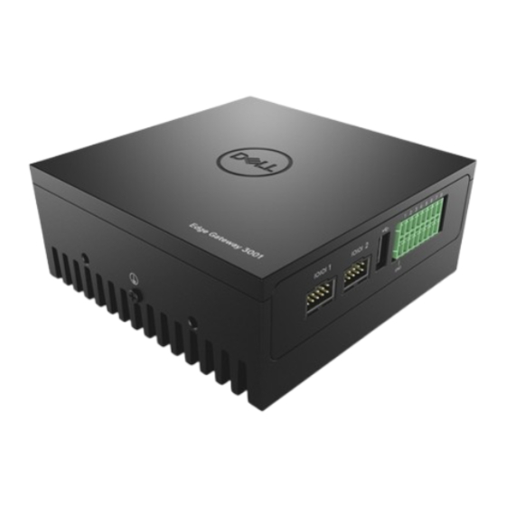
Overview The Edge Gateway 3000 Series is an Internet-of-Things (IoT) device. It is mounted at the edge of a network, enabling you to collect, secure, analyze, and act on data from multiple devices and sensors. It enables you to connect with devices used in transportation, building automation, manufacturing, and other applications. -
Page 6: Chapter 2: System Views
System views Top view Table 1. Top view Features WLAN, Bluetooth, or GPS connector Connect the antenna to increase the range and strength of wireless, Bluetooth, or satellite signals. Mobile broadband antenna-connector one (3G/ Connect the mobile broadband antenna to increase the range LTE) and strength of mobile broadband signals. -
Page 7: Left View
Table 2. Bottom view Features Service Tag label The Service Tag is a unique alphanumeric identifier that enables the Dell service technicians to identify the hardware components in your Edge Gateway and access warranty information. Earth ground A large conductor attached to one side of the power supply, which serves as the common return path for current from many different components in the circuit. - Page 8 Table 3. Left view (continued) Features To comply with EU Declaration of Conformity (DoC), ensure cable NOTE: length from the system to the device does not exceed 30 meters. To comply with regulatory requirements in Brazil, ensure cable length NOTE: from the system to the device does not exceed 10 meters.
-
Page 9: Right View
Table 4. Status-light indicators (continued) Function Indicator Color Control Status On (Amber): Low- speed connection (10 Mbps) Activity Green Driver (LAN) Off: No activity on link Blinking Green: LAN activity. The blink rate is related to packet density. The power and system status light may operate differently during different boot-up scenarios, for example, when a NOTE: USB script file is run during boot-up. - Page 10 Table 6. Right view—3001 Features RS-232/RS-422/RS-485 port one Connect a RS-232/RS-422/RS-485 cable to the Edge Gateway. Provides data transfer speeds up to 1 Mbps in RS-232 mode and 12 Mbps in RS-422/RS-485 mode. The serial port mode is configurable in the BIOS. RS-232/RS-422/RS-485 port two Connect a RS-232/RS-422/RS-485 cable to the Edge Gateway.
- Page 11 Table 8. RS-232 pin definition details (continued) Signal Characteristics Received Data Transmitted Data Data Terminal Ready Ground Data Set Ready Request To Send Clear To Send Ring Indicator Ground Table 9. RS-485/RS-422 full duplex pin definition details Signal Characteristics TXD– Transmit Data A TXD+ Transmit Data B...
- Page 12 Table 10. RS-485 half-duplex pin definition details (continued) Signal Characteristics Not applicable Not applicable Ground Not applicable Not applicable Not applicable Not applicable Not applicable Not applicable Not applicable Not applicable Ground System views...
-
Page 13: Chapter 3: Installing Your Edge Gateway
10 percent of the input DC voltage. WARNING: When installing the Edge Gateway 3001 and 3002, use a cable appropriate for the load currents: 3-core cable rated 5 A at 90°C (194°F) minimum, which conform to either IEC 60227 or IEC 60245. The system accepts cables from 0.8 mm to 2 mm. -
Page 14: Professional Installation Instructions
Professional installation instructions Installation personnel This product is designed for specific applications and needs to be installed by qualified personnel with RF and regulatory-related knowledge. The general user shall not attempt to install or change the setting. Installation location The product shall be installed at a location where the radiating antenna is kept 20 cm from nearby persons in its normal operation condition in order to meet regulatory RF exposure requirements. -
Page 15: Industry Canada Statement
● Any changes or modifications not expressly approved by the party responsible for compliance could void the user's authority to operate this equipment. ● This transmitter must not be co-located or operating in conjunction with any other antenna or transmitter. Radiation exposure statement: This equipment complies with FCC radiation exposure limits for an uncontrolled environment. - Page 16 2. Connect the antennas depending on the configuration ordered (optional). The antennas supported in the Edge Gateway vary depending on the configuration ordered. Antennas are NOTE: available in the accessory box shipped with the Edge Gateway. Table 11. Antennas supported in Edge Gateway 3001 Antennas supported Signals...
- Page 17 4. Secure the antenna by tightening the rotating head of the connector until it firmly holds the antenna in the preferred position (upright or straight). Antenna images are for illustrative purposes only. Actual appearance may differ from the images provided. NOTE: 5.
- Page 18 CAUTION: Dell recommends that you insert the micro-SIM card before turning on the Edge Gateway. Ensure that you firmly screw back the access door after closing. NOTE: Contact your service provider to activate your micro-SIM card.
- Page 19 Secondary enclosures are sold separately. NOTE: 10. Connect the Edge Gateway to one of the following power sources: ● DC-IN ● PoE Installing your Edge Gateway...
- Page 20 Ubuntu Core 16 Use the dcc.cctk command to access the Dell Command | Configure application. For more information about using the Dell Command | Configure application, see the Dell Command | Configure NOTE: Installation Guide and User's Guide at www.dell.com/dellclientcommandsuitemanuals.
-
Page 21: Activating Your Mobile Broadband Service
Activating your mobile broadband service CAUTION: Before you power on the Edge Gateway, insert a micro-SIM card. Ensure that the service provider has already activated the micro-SIM card before you use it in the Edge Gateway. NOTE: 1. Remove the screw to open the micro-SIM card access door. 2. -
Page 22: Mounting Your Edge Gateway
Example (3G): network-manager.nmcli con add type gsm ifname cdc-wdm0 con-name 3G_GSMDEMO apn internet d. Connect to the mobile network: Command line: network-manager.nmcli con up <connection-name> Example (Verizon): network-manager.nmcli con up VZ_GSMDEMO Example (AT&T): network-manager.nmcli con up ATT_GSMDEMO Example (3G): network-manager.nmcli con up 3G_GSMDEMO To disconnect from the mobile network: Command line: network-manager.nmcli con down <connection-name>... - Page 23 The mounting brackets are shipped with only those screws that are required for securing the mounting brackets to NOTE: the Edge Gateway. 1. Secure the standard-mount bracket to the back of the Edge Gateway using the four M4x4.5 screws. Torque the screws at 8±0.5 kilograms-centimeter (17.64±1.1 pounds-inch). NOTE: Installing your Edge Gateway...
- Page 24 2. Place the Edge Gateway against the wall, and align the holes in the standard-mount bracket with the holes on the wall. Screw holes on the bracket have a diameter of 3 mm (0.12 in). Installing your Edge Gateway...
- Page 25 3. Place the standard-mount bracket on the wall, and using the holes above the screw holes on the bracket, mark the positions to drill the four holes. Installing your Edge Gateway...
- Page 26 4. Drill four holes in the wall as marked. 5. Insert and tighten four screws (not supplied) to the wall. Purchase screws that fit the diameter of the screw holes. NOTE: Installing your Edge Gateway...
- Page 27 6. Align the screw holes on the standard-mount bracket with the screws and place the Edge Gateway onto the wall. Installing your Edge Gateway...
- Page 28 7. Tighten the screws to secure the assembly to the wall. Installing your Edge Gateway...
-
Page 29: Mounting The Edge Gateway Using Quick-Mount Bracket
Mounting the Edge Gateway using quick-mount bracket The quick-mount bracket is a combination of the standard-mount bracket and the DIN-rail bracket. It enables you to easily mount and demount the Edge Gateway. The mounting brackets are shipped with only those screws required for securing the mounting brackets to the Edge NOTE: Gateway. - Page 30 Mounting instructions 1. Place the standard-mount bracket on the wall, and using the holes above the screw holes on the bracket, mark the positions to drill the four holes. Installing your Edge Gateway...
- Page 31 2. Drill four holes in the wall as marked. 3. Insert and tighten four screws (not supplied) to the wall. Purchase screws that fit the diameter of the screw holes. NOTE: Installing your Edge Gateway...
- Page 32 4. Align the screw holes on the standard-mount bracket with the screws on the wall, letting the bracket hang on the screws. Installing your Edge Gateway...
- Page 33 5. Tighten the screws to secure the assembly to the wall. Installing your Edge Gateway...
- Page 34 6. Align the screw holes on the DIN-rail bracket with the screw holes at the back of the Edge Gateway. 7. Place the two M4x5 screws on the DIN-rail bracket and secure it to the Edge Gateway. Installing your Edge Gateway...
- Page 35 8. Place the Edge Gateway on the standard mount at an angle, and then pull the Edge Gateway down to compress the springs at the top of the DIN-rail bracket. Installing your Edge Gateway...
- Page 36 9. Push the Edge Gateway towards the DIN-rail to secure it on the standard-mount bracket. For more information about demounting the DIN-rail, see Demounting DIN rail. NOTE: Installing your Edge Gateway...
-
Page 37: Attaching The Cable Control Bars To The Standard-Mount Bracket
Attaching the cable control bars to the standard-mount bracket 1. Mount the Edge Gateway on the wall using the standard-mount bracket quick-mount bracket. 2. Place the cable control bar on the mounting bracket and secure it to the notch. CAUTION: Use the top cable control bar only with coaxial cable connections. - Page 38 5. Connect the cables to the Edge Gateway. 6. Loop the cable lock (not supplied) to secure each cable to the cable control bar. Installing your Edge Gateway...
-
Page 39: Mounting The Edge Gateway On A Din Rail Using The Din-Rail Bracket
Mounting the Edge Gateway on a DIN rail using the DIN-rail bracket The DIN-rail bracket includes the screws that are required for securing the bracket to the Edge Gateway. NOTE: 1. Align the screw holes on the DIN-rail bracket with the screw holes at back of the Edge Gateway. 2. - Page 40 3. Secure the DIN-rail mounting bracket to the Edge Gateway using the two M4x5 screws provided. Torque the screws at 8±0.5 kilograms-centimeter (17.64±1.1 pounds-inch) on the DIN-rail mounting bracket. NOTE: Installing your Edge Gateway...
-
Page 41: Mounting The Edge Gateway Using The Perpendicular Mount
4. Place the Edge Gateway on the DIN rail at an angle, and then pull the Edge Gateway down to compress the springs at the top of the DIN-rail mounting bracket. 5. Push the Edge Gateway towards the DIN-rail to secure the lower clip of the bracket onto the DIN rail. For more information about demounting the DIN-rail, see Demounting DIN rail. - Page 42 2. Tighten the four M4x7 screws to secure the Edge Gateway to the perpendicular-mount bracket. Torque the screws at 8±0.5 kilograms-centimeter (17.64±1.1 pounds-inch). NOTE: Installing your Edge Gateway...
- Page 43 3. Align the screw holes on the DIN-rail mount bracket with the screw holes on the perpendicular-mount bracket, and tighten the two screws. Torque the screws at 8±0.5 kilograms-centimeter (17.64±1.1 pounds-inch). NOTE: Installing your Edge Gateway...
- Page 44 4. Place the Edge Gateway on the DIN rail at an angle and push the Edge Gateway down to compress the springs on the DIN-rail mount brackets. 5. Push the Edge Gateway towards the DIN-rail to secure the lower clip of the bracket onto the DIN rail. Installing your Edge Gateway...
-
Page 45: Mounting The Edge Gateway Using A Vesa Mount
6. Secure the Edge Gateway on the DIN rail. Mounting the Edge Gateway using a VESA mount The Edge Gateway can be mounted on a standard VESA mount (75 mm x 75 mm). The VESA mount option is sold separately. For VESA mounting instructions, see the documentation that is shipped NOTE: with the VESA mount. - Page 46 Installing your Edge Gateway...
-
Page 47: Chapter 4: Setting Up The Zigbee Dongle
Setting up the ZigBee dongle CAUTION: Do not connect the ZigBee dongle if the Edge Gateway is installed inside the enclosure. 1. Power off your Edge Gateway. 2. Connect the ZigBee dongle to any external USB port on your Edge Gateway. 3. -
Page 48: Chapter 5: Setting Up The Operating System
Setting up the operating system CAUTION: To prevent operating system corruption from sudden power loss, use the operating system to gracefully shut down the Edge Gateway. The Edge Gateway is shipped with one of the following operating systems: ● Windows 10 IoT Enterprise LTSB 2016 ●... -
Page 49: Windows 10 Iot Enterprise Ltsb 2016 Basic Functions
NOTE: Cloud LED To utilize the Cloud LED, download the necessary tools and drivers from www.dell.com/support. NOTE: One unique feature of the Edge Gateway 3000 Series is the Cloud LED. Cloud LED enables you to visually inspect the operational status of the Edge Gateway by looking at the display light on the left panel of the Edge Gateway. -
Page 50: Bluetooth Configuration
Bluetooth configuration In the Search box, type Settings and open the Settings window. Select Devices, and then select Bluetooth from the menu on the left panel to configure the network. WWAN (5815) network configuration Ensure that the micro-SIM card is already activated by your service provider before using it in the Edge Gateway. NOTE: For more information, see activate your mobile broadband... -
Page 51: Updating Operating System And Applications
Updating operating system and applications After enabling the network connections and connecting to the internet, Dell recommends to have the latest OS components and applications installed. To update Ubuntu Core 16, run: admin@localhost:~$ sudo snap refresh... - Page 52 Identifying the System Service Tag Run the command: admin@localhost:$ cat /sys/class/dmi/id/ product_serial The system tag is printed. Identifying the system vendor Run the command: admin@localhost:$ cat /sys/class/dmi/id/ board_vendor returns Dell Inc. The system tag is printed. Setting up the operating system...
-
Page 53: Ubuntu Network Manager
Ubuntu Network Manager Network-Manager is a native Ubuntu Snappy connection manager. The application can be used to configure the Edge Gateway so that it's automatically-detected and connected to the network. The application can be used to configure multiple network devices. A command-line utility nmcli is included with Network-Manager to support non-graphical user interface configurations. -
Page 54: Connecting Through Bluetooth
Connecting through WLAN 1. Show a list of network interfaces like eth0, eth1, wlan0, mlan0, and so on. $ network-manager.nmcli d 2. Show a list of network interfaces like eth0, eth1, wlan0, mlan0, and so on. $ network-manager.nmcli d 3. Show a list of available wireless access points. $ network-manager.nmcli device wifi list 4. - Page 55 2. Run the command to power on the Bluetooth device. $power on 3. Register the agent for the keyboard: $agent KeyboardOnly $default-agent 4. Run the command to put the Bluetooth controller in pair-able mode. $pairable on 5. Run the command to scan for nearby Bluetooth devices. $scan on 6.
-
Page 56: Bluetooth Serial Port Profile (Spp)
[bluetooth]# scan off 3. Pair with each other. As of Bluetooth v2.1, Secure Simple Pairing is a requirement, and offers three methods of pairing devices, which are applicable on the Dell Gateway 3000 series: ● Just Works ● Numeric Comparison ●... -
Page 57: Serial Ports
RS-232 Ready-to-use software to control or manage devices are not available from Dell. To configure the RS-232 port, run the following commands: 1. Set RS232 from the pre-installed DCC application. $ dcc.cctk -h --serial1 $ dcc.cctk --serial1... -
Page 58: Minicom
1. Set RS-422/RS-485 FD from the pre-installed DCC application. dcc.cctk -h --serial1 dcc.cctk --serial1 dcc.cctk --serial1=rs422 2. Set serial port mode. $ sudo stty -F /dev/ttyXRUSB0 ispeed 115200 ospeed 115200 -echo -onlcr -ixon -ixoff $ sudo stty -F /dev/ttyXRUSB1 ispeed 115200 ospeed 115200 -echo -onlcr -ixon -ixoff 3. - Page 59 1. Install Minicom. $ sudo snap install classic --devmode --beta $ sudo classic.create $ sudo classic $ (classic) sudo apt-get update $ (classic) sudo apt-get install minicom 2. Set Minicom. $ sudo minicom -s 3. Select Serial port setup. 4. Press A to edit the Serial Device to ttyUSB0. This can be any other value if there is more than one USB serial cable attached.
-
Page 60: Gpio
For more information on GPIO sysfs interface, see https://www.kernel.org/doc/Documentation/gpio/sysfs.txt. NOTE: The GPIO connector (AD5593R) on the Edge Gateway 3001 has 8 pins. The connector can controlled by the standard Linux GPIO.The GPIOs number maps 330 to 337. 1. Pin: GPIO1 2. -
Page 61: Watchdog Timer (Wdt)
NOTE: Watchdog.html. Dell recommends that you enable the WDT by default to activate the fail-safe circuitry. Snappy, a WDT-compatible operating system, provides the capability to detect and recover the system from malfunctions or unexpected crashes. To check daemon status, run the command: admin@localhost:$ systemctl show | grep –i watchdog... -
Page 62: Snappy Auto Update/Autopilot
● Device node for NMEA streaming: Edge Gateway 3001/3003 $ cat /dev/ttyS4 To access location service: $ sudo locationd.monitor Enabled position/heading/velocity updates... Update(Position(lat: 26.9511 deg, lon: 155.087 deg, alt: n/a, hor.acc.: n/a, ver.acc.: n/a), 1489044234694526189) Update(0.552 m s^-1, 1489044234695698701) Update(Position(lat: 26.9477 deg, lon: 155.098 deg, alt: n/a, hor.acc.: n/a, ver.acc.:... -
Page 63: Sensors
deb packages. Please see 'snap --hwlp' for app installation and transactional updates. Last login: Tue Nov 01:10:12 2016 from 10.101.46.187 Admin@localhost:~$ sudo snapweb.generate-toen Snapweb Access Token: GtYaoevIodhTgHDyFWczWtYkEhDYROpX0pf27K62TtTOVooUwRuQ)IgBB7ECznCP Use the above token in the Snapweb interface to be granted access. admin@localhost:~$ 5. -
Page 64: Ignition Pin
Retrieving raw data from sensors ● To query sensor devices, run the command. $ cat /sys/bus/iio/devices/iio:device*/name hts221 <-- device0, Humidity and temp. lng2dm_accel <-- device1, G-sensor lps22hb <-- device2, Pressure ● To retrieve data from the humidity and temperature sensor, run the command. $ cat in_humidityrelative_offset $ cat in_humidityrelative_raw $ cat in_humidityrelative_scale... -
Page 65: System Power Management
Specify the action to take when the power button is pressed. Table 20. Values and configuration options for the ignition pin ignore Do nothing poweroff (default) Shut down the system reboot Reboot the system halt Halt the system kexec Direct-boot a new kernel suspend Suspend the system hibernate... -
Page 66: Restoring Ubuntu Core 16
4. Recheck the support status. $ sudo iw phy phy0 wowlan show 5. Make sure wlan0 is up and running with IP address. 6. Perform sleep. $ sudo systemctl sleep Or, perform hibernation. $ sudo systemctl hibernate 7. Use another system to wake from wlan (Supported tools: wakeonlan, and etherwake). $ sudo wakeonlan MAC $ sudo etherwake MAC Restoring Ubuntu Core 16... -
Page 67: Flashing A New Os Image
● Ubuntu Desktop ISO You can download the latest version of the Ubuntu Desktop ISO file from http://releases.ubuntu.com. NOTE: ● A released Ubuntu Core 16 image from Dell.com/support: <unique name-date> img.xz ● USB keyboard ● USB mouse ● Ubuntu workstation with Ubuntu Desktop 14.04 or higher Flashing new Ubuntu OS image 1. -
Page 68: Ubuntu Server
The dd command erases the content of the drive it writes to. CAUTION: b. Type the following command and press Enter. xzcat <unique name-date>img.xz | sudo dd of=/dev/sda bs=32 ; sync The sda may have to be replaced with the actual name of the drive on the system. NOTE: 4. -
Page 69: Installing Or Configuring Dynamic Host Configuration Protocol (Dhcp) Daemon
Installing or configuring Dynamic Host Configuration Protocol (DHCP) daemon For more information about Dynamic Host Configuration Protocol (DHCP), see: ● help.ubuntu.com/lts/serverguide/dhcp.html.en ● help.ubuntu.com/community/isc-dhcp-server Installing dhcpd At a terminal prompt, enter the following command to install dhcpd: # sudo apt install isc-dhcp-server You may need to edit /etc/default/isc-dhcp-server to specify the interfaces dhcpd should listen to. -
Page 70: Firmware Management On Ubuntu Server
UEFI BIOS firmware, in compliance with LVFS requirements. NOTE: For additional information on how to update the firmware under Linux, see en.community.dell.com/techcenter/b/techcenter/ archive/2016/02/02/dell-firmware-updating-under-linux. Ubuntu Server firmware update—Online method Follow these steps to update the Ubuntu Server firmware automatically. -
Page 71: Configure Watchdog Timer (Wdt)
Ubuntu Server firmware update—Manual method Follow these steps to update the Ubuntu Server firmware manually. Search for the Edge Gateway firmware.cab file at fwupd.org/lvfs/devicelist and copy it to the target device. 1. Display all devices detected by the fwupd command. # sudo fwupdmgr get-devices 2. -
Page 72: Trusted Platform Module (Tpm)
TPM hardware is installed on products with Snappy-enhanced security support. TPM is supported only on these devices that have the TPM hardware installed. The TPM on/off setting is configurable in the BIOS and manageable through the Dell Command | Configure application in the operating system. -
Page 73: Cloud Led On/Off
Cloud LED On/Off Cloud LED enables you to visually inspect the operational status of the Edge Gateway by looking at the display light on the left panel of the Edge Gateway. 1. To export Cloud LED PIN, run the command: #sudo su –... -
Page 74: Global Positioning Systems (Gps)
GPIO-port pin definition details. NOTE: Configure serial ports To configure the serial ports, run the following commands in the Dell Command | Configure application: 1. Adjust the mode in Dell Command | Configure. $ cctk -h --serial1 $ cctk --serial1 $ cctk --serial1=rs232 Mode options can be rs232, rs422 or rs485. -
Page 75: Gpio
For more information on GPIO sysfs interface, see kernel.org/doc/Documentation/gpio/sysfs.txt. NOTE: The GPIO connector (AD5593R) on the Edge Gateway 3001 has 8 pins. The connector can controlled by the standard Linux GPIO interface. The GPIOs number maps 330 to 337. 1. Pin: GPIO1 2. -
Page 76: Sensors
ADC/DAC mode Using the Dell Command | Configure application, you can switch GPIO to ADC (Analog-to-Digital Converter) or DAC (Digital- to-Analog Converter) mode. For more information, see the Dell Command | Configure Version 3.3 Command Line Interface Reference Guide at www.dell.com/support. -
Page 77: Ignition Pin
Converting raw data for use Apply the formula in the table to convert the raw data collected into usable measurements. Table 27. Convert relative humidity and temperature sensor raw data Relative humidity and temperature sensor ST Micro HTS221 RH (in %) = (in_humidityrelative_raw + in_humidityrelative_offset) * in_humidityrelative_scale Temperature (degC) = (in_temp_raw + in_temp_offset) * in_temp_scale Table 28. -
Page 78: System Power Management
Configuring system wake-up from low-power states (S3/S4/S5)—WLAN 1. Enable Wake on WLAN in the BIOS program. For more information on accessing the BIOS program, see Accessing BIOS settings. Alternatively, use Dell Command | Configure. # sudo /opt/dell/dcc/cctk --wakeonlan=enablewakeonwlan 2. Connect the system to a wireless network. -
Page 79: Ubuntu Network Manager
1. Enable Wake on LAN in the BIOS program. For more information on accessing the BIOS program, see Accessing BIOS settings. Alternatively, use Dell Command | Configure. # sudo /opt/dell/dcc/cctk --wakeonlan=enable 2. Enable Wake on LAN in nmcli (enabled by default). - Page 80 Connecting through WWAN For more information on configuring and connecting through WWAN, see docs.ubuntu.com/core/en/stacks/ NOTE: network/network-manager/docs/configure-cellular-connections. 1. Check if a modem is present and identify the modem index number. # sudo mmcli –L 2. Check the modem status and identify the primary port. # sudo mmcli -m<0>...
- Page 81 Connecting through WLAN 1. Show a list of network interfaces like eth0, eth1, wlan0, mlan0, and so on. # nmcli d 2. Show a list of available wireless access points. # nmcli d wifi 3. Wireless connection with nmcli: Run the following commands and replace $SSID, $PSK, and $WIFI_INTERFACE with the variables for your environment.
- Page 82 2. Create your own /etc/hostapd/hostapd.conf. For example: auth_algs=1 beacon_int=50 channel=3 country_code=ES disassoc_low_ack=1 driver=nl80211 hw_mode=g ht_capab= ieee80211d=1 ieee80211n=1 interface=wlan0 require_ht=0 rsn_pairwise=CCMP ssid=TEST wmm_enabled=1 wpa=2 wpa_key_mgmt=WPA-PSK wpa_passphrase=00000000 3. Disable wpa_supplicant. # sudo systemctl stop wpa_supplicant.service # sudo systemctl mask wpa_supplicant.service 4. Detach from network manager. # sudo nmcli d set wlan0 managed no 5.
- Page 83 8. Enter the PIN code on the Bluetooth keyboard, if needed. 9. Run the following command to trust the Bluetooth keyboard. # trust <MAC address of Bluetooth keyboard> 10. Run the following command to connect to the Bluetooth keyboard. # connect <MAC address of Bluetooth keyboard> 11.
-
Page 84: Restoring Ubuntu Server
● Service Tag of the Edge Gateway ● .NET Framework 4.5.2 or higher ● A Windows computer with administrator rights and at least 8 GB of available storage space to download the Dell ISO recovery image ● A blank USB flash drive with at least 8 GB of storage space. - Page 85 4. Click Yes in the User Account Control prompt. 5. Connect the USB flash drive to the computer. 6. Click Browse and navigate to the location where the Dell ISO recovery image file is saved. 7. Select the Dell ISO recovery image file and click Open.
-
Page 86: Chapter 6: Accessing And Updating Bios
● On the connected computer running Ubuntu Core, access Dell Command | Configure using the command dcc.cctk For more information on how to use the Dell Command | Configure application, see the Dell Command | Configure Installation Guide and User's Guide at www.dell.com/dellclientcommandsuitemanuals. -
Page 87: Updating The Bios On A Windows System
The fwupgmgr tool or commands are used to update the UEFI BIOS on the system. The UEFI BIOS for this platform is released through online Linux Vendor File System (LVFS) based methods Dell recommends that you enable the UEFI Capsule update by default so that it is running in the background to keep the system BIOS up to date. -
Page 88: Dell Command | Configure (Dcc)
Connect and login to the Edge Gateway with one these options: NOTE: ● Remote system configuration (only for Edge Gateway 3001 and 3002) 2. Check the current BIOS details. $sudo uefi-fw-tools.fwupdmgr get-devices 3. Check if the update is available from LVFS service. -
Page 89: Security (Bios Level 1)
Table 33. System configuration (BIOS level 1) (continued) BIOS level 2 BIOS level 3 Item Default value [Disabled, Enabled, Enabled Enabled w/PXE w/PXE] Serial Port1 [Disable, RS232, RS-485 RS232 HALF DUPLEX, RS-485/422 FULL DUPLEX] Serial Port2 [Disable, RS232, RS-485 RS232 HALF DUPLEX, RS-485/422 FULL DUPLEX] USB Configuration... -
Page 90: Secure Boot (Bios Level 1)
Table 34. Security (BIOS level 1) (continued) BIOS level 2 BIOS level 3 Item Default value Strong Password Strong Password Enable Strong Password Disabled [Enable/Disable] Password Configuration Password Configuration Admin Password Min Admin Password Max Password Bypass Password Bypass [Disabled/Reboot Bypass] Disabled Password Change Password Change... -
Page 91: Performance (Bios Level 1)
Table 35. Secure boot (BIOS level 1) (continued) BIOS level 2 BIOS level 3 Item Default value Expert Key Management Expert Key Management Enable Custom Mode Disabled [Enable/Disable] Custom Mode Key Management {PK/KEK/db/ dbx} Performance (BIOS level 1) Table 36. Performance (BIOS level 1) BIOS level 2 BIOS level 3 Item... -
Page 92: Virtualization Support (Bios Level 1)
Table 38. POST behavior (BIOS level 1) (continued) BIOS level 2 BIOS level 3 Item Default value Keyboard Errors Keyboard Errors Enable Keyboard Error Enabled Detection [Enable/Disable] Fastboot Fastboot [Minimal/Thorough/Auto] Thorough Extend BIOS POST Time Extend BIOS POST Time [0 seconds/5 seconds/10 0 seconds seconds] Warnings and Errors... -
Page 93: System Logs (Bios Level 1)
System logs (BIOS level 1) Table 41. System logs (BIOS level 1) BIOS level 2 BIOS level 3 Item Default value BIOS Events BIOS Events List of BIOS events with Not applicable "Clear Log" button to clear the log Accessing and updating BIOS... -
Page 94: Chapter 7: References
● Dell Command | Configure Reference Guide ● Dell Command | Monitor User's Guide ● Dell Command | PowerShell Provider User's Guide For more information on using Dell Data Protection | Encryption see the documentation for the software at www.dell.com/ support/manuals. -
Page 95: Chapter 8: Appendix
Use only the supplied or an approved replacement antenna. NOTE: Modifications to the device or use of unauthorized antennas not expressly approved by Dell is the sole responsibility NOTE: of the user, configurator or operator, who must reassess the equipment in accordance to all applicable international Safety, EMC, and RF standards. -
Page 96: De-Mounting From Din-Rail Bracket
Table 43. Mobile broadband auxiliary antenna maximum gain (dBi) (continued) Antenna position—Bent Antenna position—Straight Frequency (MHz) 4G (dBi) 4G (dBi) 1710~1880 1850~1990 1920~2170 Table 44. WLAN/GPS antenna maximum gain (dBi) Antenna position—Bent Antenna position—Straight Frequency (MHz) GPS (dBi) WLAN (dBi) GPS (dBi) WLAN (dBi) Not applicable... -
Page 97: Boot Up And Login-Static Ip System Configuration
The first-time boot to Windows takes about 5 minutes for system configuration. Subsequent boot-ups take NOTE: about 50 seconds. 2. Using the MAC address provided on the front cover of the Edge Gateway, obtain the IP address through your network’s DHCP server or through a network analyzer. - Page 98 ● IP address: 192.168.2.1 ● Subnet mask: 255.255.255.0 ● DHCP server: Not applicable 1. On the host computer, configure the Ethernet adaptor that is connected to the Edge Gateway with a static IPv4 address under the same subnet. Set the IPv4 address to 192.168.2.x (where x represents the last digit of the IP address, for example, 192.168.2.2).
-
Page 99: Chapter 9: Contacting Dell
2. Verify your country or region in the drop-down list at the bottom of the page. 3. Select the appropriate service or support link based on your requirement or choose the method of contacting Dell that is convenient for you.
Need help?
Do you have a question about the Edge Gateway 3001 and is the answer not in the manual?
Questions and answers