
Related Manuals for OMP Hobby OMPP004R


Summary of Contents for OMP Hobby OMPP004R
- Page 1 Global Professional RC Model Brand Installation Manual OMPHOBBY 60” 70E Edge 540 Kevlar Reinforced Balsa Airplane Zhuhai Edge Smart Drive Technology Co., Ltd. www.omphobby.com...
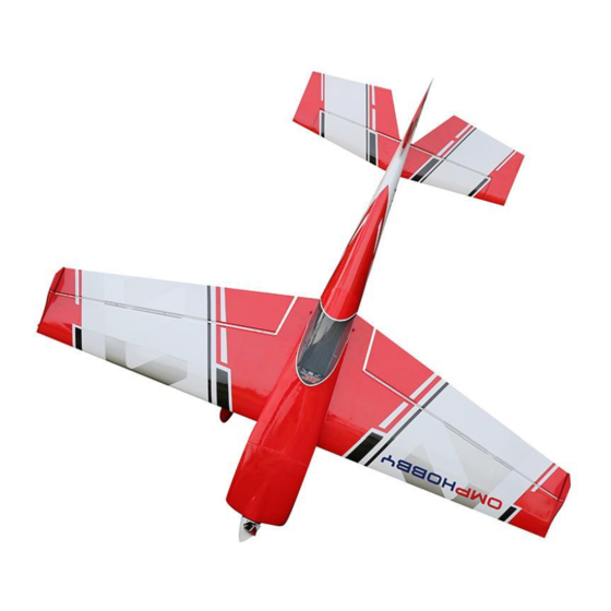
- Page 2 OMPHobby 60” Balsa Airplane OMPHobby 60” 70E EDGE 540, not only has the low speed stability, low stall point, excellent 3D performance, but also very fast roll rate of traditional EDGE, and precise navigation control. The traditional securing method of the motor base and the landing skid base have been changed, preventing the loosening of the anti-grasping nut.
- Page 3 OMPHobby 60” Balsa Airplane Parameter Specification Green-Black Red-White Item: OMPHOBBY 60”EDGE 540 Color Option Yellow-White Orange-White 1524mm(61in) 1500mm(60in) WingSpan: Full Length: The Center of Flight Weight: 2.75~2.85KG Approx.86-95mm Gravity (CG): Wing Area: 42.32d㎡ Wing Load: 64.98~67.34g/d㎡ Wing Angle of Motor Thrust 0°...
- Page 4 OMPHobby 60” Balsa Airplane Ø Package contents (ARF version) Ø Tools and Gear needed Zhuhai Edge Smart Drive Technology Co., Ltd. www.omphobby.com...
- Page 5 Cowl and Engine Assembly Ø Motor Installation 1. Unscrew socket head screws from the head plate of fuselage. 2. Put the screws into motor mount and put aluminum columns to the other side of screws. 3. Apply glue to the screws and install motor to motor holder. Ø...
- Page 6 Cowl Part Assembly Ø Cowl , Propeller, Spinner Installation 1. Install cowl to fuselage (please take note that motor must be in center position) 2. Remove the propeller spinner adapter and screw gasket, install the aluminum spinner back-plate, propeller, propeller spinner adapter and screw gasket in succession.
- Page 7 Landing gear Assembly Ø Landing Gear Installation 1. Unscrew hexagon screws on the landing gear plate. 2. Apply glue to hexagon screws, use it to secure the carbon fiber landing gear to landing gear plate. 3. Put landing gear cover plate into slot and stick it with transparent tape.
- Page 8 Landing gear Assembly 6. Install wheel cowls, tighten screws. Tail wheel Assembly Ø Tail Wheel Installation 1. Find the securing hole of the tail wheel frame, secure the tail wheel bracket with screws. Zhuhai Edge Smart Drive Technology Co., Ltd. www.omphobby.com...
-
Page 9: Installation
Elevator Assembly Ø Elevator Servo Installation 1. Find 60-core extension cable on fuselage, tear off the sticker, then connect it with elevator servo. 2. Find the white polyester thread in fuselage frame, gently pull it until the servo is placed into the opened servo hole. 3. - Page 10 Elevator Assembly Ø Horizontal Tail Installation 2. Use sand paper to roughen the root of control arm. Try to insert it into the mounting slot to adjust the position at first, then take it out, apply glue to the slot and the root of the control arm, insert it to the slot to secure it.
- Page 11 Elevator Assembly Ø Horizontal Tail Installation 5. After the glue is dried, assemble the servo arm and control arm with ball head pull rod, secure the cup head hexagonal screw, gasket, ball head to the servo arm, secure it with iron pliers, adjust the ball head pull rods to proper length.
- Page 12 Rudder Assembly Ø Rudder Installation 1. Carefully locate the slot which has been made on the vertical tail, lightly cut through the covering but not into the balsa sheeting. 2. Grind the root of control arms, try it first to insert it into the slot to adjust the position, then take it out, apply glue to the slot and the root of the control arm, insert it to the slot...
- Page 13 Rudder Assembly 6. Apply grease or engine oil on all joints between rudder and fuselage, and around the hinges, to avoid affecting the sensitivity of rudder after glue dried. 7. Tie rudder with masking tape while glue is still wet to prevent loosening.
- Page 14 Wings Assembly Ø Aileron Servo Installation 1. Carefully locate the slot which has been made on the wing tail, lightly cut through the covering but not into the balsa sheeting. 2. Use sand paper to roughen the root of control arm. Try to insert it into the mounting slot to adjust the position at first, then take it out, apply glue to the slot and the root of the control arm, insert it to the slot to secure it.
- Page 15 Wings Assembly 5. Remove black rubber ring from the wing side,pass aileron servo wire into the black rubber ring and secure it to the original position. 6. Secure aileron servo arm and control arms with ball head pull rod, put the cup head hexagonal screw, gasket, ball head on servo arm, secure it with iron pliers, adjust the ball head pull rods to proper length.
- Page 16 Wings Assembly 9. Assemble the wing tube into the fuselage then install wings, turn white screws to secure the wings. 10. Unscrew the retaining screws on the wing, install wingtip. Connect Receiver and Battery Zhuhai Edge Smart Drive Technology Co., Ltd. www.omphobby.com...
- Page 17 Guarantee The KAVAN Europe s.r.o. products are covered by a guarantee which fulfils the currently valid legal requirements in your country. If you wish to make a claim under guarantee, please contact the retailer from whom you first purchased the equipment. The guarantee does not cover faults which were caused in the following ways: crashes, improper use, incorrect connection, reversed polarity, maintenance work car- ried out late, incorrectly or not at all, or by unauthorised personnel, use of other than genuine KAVAN Europe s.r.o.
Need help?
Do you have a question about the OMPP004R and is the answer not in the manual?
Questions and answers