Advertisement
Quick Links
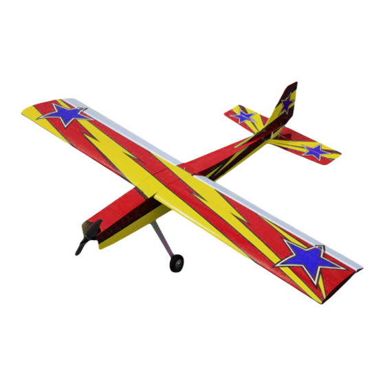
CHALLENGER
CHALLENGER
OMP Hobby 49" Challenger is a sport RC model airplane built in the traditional way: balsa and film cover.
The airplane features light yet strong structure, low wing load, and abundant power, making the airplane
easy to fly and capable of a lot of advanced aerobatics, such as all P3A and a few 3D maneuvers. This
airplane performs very well in either low or high speed, with great authenticity and precision in response to
radio stick movements, ideal for pilots who graduated from trainer airplanes to the next level of skills.
The optional 49" Challenger receiver ready version is an almost completed kit in factory. Motor, ESC,
servos, Ailerons, elevator, are all installed. Landing gear is preassembled. Propeller is included in the kit. It
takes no more than an hour to put the kit together and ready for the sky.
Wingspan
49 in(1250mm)
Wing Area: 28dm² or 434 in²
(3.01 ft²)
Motor: Sunnysky X2820
1100KV Outrunner
Propeller: SunnySky Eolo
12x6.5" electric propeller
www.OMPHobby.com
Specifications and Parts Recommendations
Length
39.6 in(1006mm)
Wing Loading: 41.8g/dm²
or 13.7oz/ft²
ESC: SunnySky 40A with 5V
3A BEC
Servos: 4 of 17g OMPHOBBY
metal gear digital servos.
CG: 62mm from the leading
Flying Weight: 1170g or 41.3oz
Battery: 3S 11.1V LiPo,
2200mAh (optional)
Flight time: 5~10 minutes
www.OhioModelProducts.com
edge of main wings
Advertisement

Related Manuals for OMP Hobby Challenger


Summary of Contents for OMP Hobby Challenger
- Page 1 CHALLENGER CHALLENGER OMP Hobby 49” Challenger is a sport RC model airplane built in the traditional way: balsa and film cover. The airplane features light yet strong structure, low wing load, and abundant power, making the airplane easy to fly and capable of a lot of advanced aerobatics, such as all P3A and a few 3D maneuvers. This airplane performs very well in either low or high speed, with great authenticity and precision in response to radio stick movements, ideal for pilots who graduated from trainer airplanes to the next level of skills.
- Page 2 CHALLENGER CHALLENGER Two color schemes available Package contents (receiver ready version) 1. Fuselage 2. Left half wing 3. Right half wing 4. Horizontal stabilizer 5. Rudder 6. Tube 7. Tail wheel 8. Link rods 9. Adhesive Velcro 10. Landing gear 11. Propeller...
- Page 3 The following descriptions apply to the receiver ready version only. Not all parts and assembly works are available in the ARF version. *Main landing gear has been assembled in factory. *All ball tie rods are preassembled. *All servo horns have already been installed. *All ball joints have been installed. *Hinge slots are cut in factory. *Servo leads taped for easy access. *ESC, motor, and servos are installed in factory.
- Page 4 Installation of Horizontal Stabilizer Cut off a small piece of cover film to expose the hole used for holding the steel of tail wheel. Attach tail horizontal stabilizer to the fuselage. Install the T-shaped plate to the tail and secure it with screws.
- Page 5 Installation of Elevator and Tail Wheel Drill a hole in the rudder that will hold the steel wire of tail wheel. Insert the steel wire of tail wheel through the hole in horizontal stabilizer. Align steel wire and hinges and put vertical stabilizer and rudder together.
-
Page 6: Landing Gear Installation
Landing Gear Installation The mounting screws of landing gear are installed on the fuselage to prevent missing parts. Take out the screws from the bottom of fuselage with 2.5mm Alan screwdriver. Align the landing gear to the hole locations and tighten the three screws. Application of threadlocker is highly recommended. - Page 7 Installation of Servo Link Rods 1. Servo horns are installed at center position in factory. Hook servos to a receiver to check center point if necessary. 2. Level the control surfaces, and set rudder arms at 90 degree positions. 3. Adjust the link rod length by turning the ball joints to appropriate positions.
-
Page 8: Installation Of Propeller
Installation of Servo Link Rods (continued) 5. Electrify the servos to make sure all the control surfaces are installed in the center positions. Installation of Propeller... - Page 9 Recommended Settings of Dual Rates and Exponentials of Control Surfaces Low rate Low rate exp High rate High rate exp Ailerons Elevator Rudder Flaps For customer support in the USA, please For customer support outside of the USA, contact Ohio Model Products in Ohio. please contact OMPHobby in China. Tel: +1‐614‐733‐9488 (9am ‐5pm, ET) Tel: +86‐755‐8672‐4337 Email: support@omphobby.com Email: sales@omphobby.com Website: www.OhioModelProducts.com Website: www.OMPHOBBY.com Disclaimer and Safety • This product is not a toy. It is not recommended for children under age 14. • Fly the airplane by abiding by local laws and rules. • Fly the airplane in a designated location, and always maintain visual contact of the aircraft. • Avoid flying directly over unprotected people, moving vehicles, and occupied structures. • Read the safe code of AMA before flight. The guideline can be downloaded from the following link: www.modelaircraft.org/files/100.pdf...
Need help?
Do you have a question about the Challenger and is the answer not in the manual?
Questions and answers