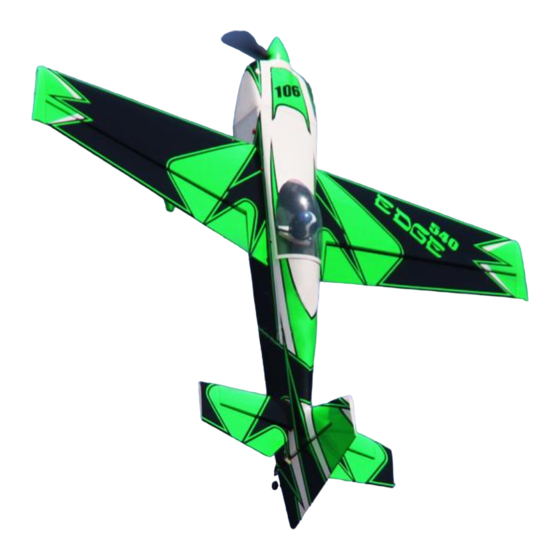
Summary of Contents for OMP Hobby Edge 540
- Page 1 Global Professional RC Model Brand Installation Manual OMPHOBBY 106” Edge 540 Kevlar Reinforced Balsa Airplane Zhuhai Edge Smart Drive Technology Co., Ltd. www.omphobby.com...
- Page 2 OMPHobby 106” Balsa Airplane Zhuhai Edge Smart Drive Technology Co., Ltd. www.omphobby.com...
- Page 3 OMPHobby 106” Edge540 Balsa Airplane Options: Three colors for choosing : Orange-White, Green-Black, Red-White Unboxing-What’s in the Box? Zhuhai Edge Smart Drive Technology Co., Ltd. www.omphobby.com...
- Page 4 Landing gear Assembly Landing Gear Installation 1. Landing gear parts 2. Install wheels, secure wheels with gasket and screw. (Apply threadlocker to screws) 3. Put the cuff through the land gear before install the wheel 4. Unscrew hexagon screws on the landing gear plate, apply threadlocker to hexagon screws, use it to secure the carbon fiber landing gear to landing gear plate. 5. Put landing gear cover plate into a slot and stick it with transparent tape. Zhuhai Edge Smart Drive Technology Co., Ltd. www.omphobby.com...
- Page 5 Landing gear Assembly 6. Secure the cuffs with screws. Be careful to not break the screws. If the screw seems to be difficult to insert use a drill to open up the hole. (Some people have found they prefer a dob of silicone inside the cuff hold them secure.) Tail wheel Assembly Tail Wheel Installation Install the tail wheel assembly using washers and socket head screws. Please apply anaerobic adhesive and lock three M3 fixing screws before installation. Zhuhai Edge Smart Drive Technology Co., Ltd. www.omphobby.com...
- Page 6 Control Horns Assembly 1. Carefully locate the slots which have been made on elevators, ailerons, rudder, lightly cut through the covering but not into the balsa sheeting. 2. Use sand paper to scuff the root of control horns for a good glue bond. Try to insert it into the mounting slots to adjust the position first. 3. Put the control horns reinforcing piece, drop the horns in the holes,positioned correctly when the horns are directly above the hinge line,then stick masking tape around the reinforcing piece as shown in the picture, cut about 1mm inside with a knife and remove the covering, below to expose the pre‐cut slots. Zhuhai Edge Smart Drive Technology Co., Ltd. www.omphobby.com...
- Page 7 Control Horns Assembly 4. Apply epoxy inside the pre‐cut slots, and coat the horns with epoxy as shown. 5. Fit the horns into the locking plate and then insert them into the pre‐cut slots. Align the right and left sides before the epoxy cures. Wipe away excess epoxy with rubbing alcohol. Zhuhai Edge Smart Drive Technology Co., Ltd. www.omphobby.com...
- Page 8 Servo Assembly Elevator Servo Assembly Install servos as shown with the servo label facing toward the rear of the fuselage. Install the servo arm in the vertical position. Adjust the pushrod length so that the servo and elevator are both in the neutral position. Zhuhai Edge Smart Drive Technology Co., Ltd. www.omphobby.com...
- Page 9 Engine and the throttle servo installation Measure the length of the engine from the firewall to the prop thrust washer. Measure the distance required for the prop thrust washer to clear the front of the cowl by ¼” to ½”then mark the firewall position on the engine mount. Or use the engine mounting hole board from spare parts bag to mark and drill the holes. Cut out from paperboard or cardboard as a template for vent hole Zhuhai Edge Smart Drive Technology Co., Ltd. www.omphobby.com...
- Page 10 Engine and the throttle servo installation Before installing the air deflector, please clamp the cowl to determine the gap with the cylinder and trim it, then use epoxy glue to fix Zhuhai Edge Smart Drive Technology Co., Ltd. www.omphobby.com...
- Page 11 Engine and the throttle servo installation Oil circuit installation diagram Use an electric soldering iron to open the covering over the vent holes Zhuhai Edge Smart Drive Technology Co., Ltd. www.omphobby.com...
- Page 12 Recommended Settings of Dual Rates and Exponentials of Control Surfaces Low rate Low rate exp High rate High rate exp Aileron servo 10-20° 30-50% 35-40° 60-70% Elevator 15-25° 30-50% 45-55° 60-70% Rudder 30-40° 35-55% 40-55° 65-75% The preferred CG for this plane is at 170mm back from the leading measured at the wingtip Zhuhai Edge Smart Drive Technology Co., Ltd. www.omphobby.com...
- Page 13 Guarantee The KAVAN Europe s.r.o. products are covered by a guarantee which fulfils the currently valid legal requirements in your country. If you wish to make a claim under guarantee, please contact the retailer from whom you first purchased the equipment. The guarantee does not cover faults which were caused in the following ways: crashes, improper use, incorrect connection, reversed polarity, maintenance work car- ried out late, incorrectly or not at all, or by unauthorised personnel, use of other than genuine KAVAN Europe s.r.o.


Need help?
Do you have a question about the Edge 540 and is the answer not in the manual?
Questions and answers