Table of Contents
Advertisement
Quick Links
Advertisement
Table of Contents

Subscribe to Our Youtube Channel
Related Manuals for Insportline Verticon Pro 500


Summary of Contents for Insportline Verticon Pro 500
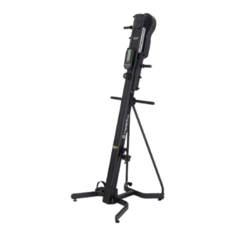
- Page 1 USER MANUAL – EN IN 25973 Verticon inSPORTline Pro 500...
-
Page 2: Table Of Contents
CONTENTS SAFETY INSTRUCTIONS ........................3 PARTS LIST ............................4 ASSEMBLY ............................. 5 CONTROL PANEL ..........................9 Buttons ..............................9 PROGRAMS ............................9 Quick start ............................9 Target exercise ..........................10 HRC 65% ............................11 HRC 85% ............................12 Virtual landmark ..........................13 Assitional information ......................... -
Page 3: Safety Instructions
SAFETY INSTRUCTIONS • Read the manual carefully before first use and assembly and keep it for future reference. • Only assemble the device on a flat and clean surface so as not to affect its functionality. • Clean the device regularly. Metal parts can easily rust. •... -
Page 4: Parts List
PARTS LIST Name Qty. Main frame Rear base Holder - left Holder - right Connection frame Front base Reinforcement frame - left Reinforcement frame - right Handles Pedal - left Pedal - right... -
Page 5: Assembly
Name Qty. Bolt M8 * P1.25 * 25 Bolt M8 * P1.25 * 20 Bolt M8 * P1.25 * 25 Spring washer - M8 Flat washer - ∮8x∮19 * 3.0t Bolt M8 * P1.25 * 45 Arc washer - ∮8x∮19-R19 * 1.5t Axle Allen key - 6mm * 40 mm * 120 mm Wrench –... - Page 6 Step 2 Attach the holders (C and D) to the frame (A). Fix the holders (C and D) using the shaft (h), bolts (b), spring washer (d) and washer (e) see picture. Pay attention to the left and right side.
- Page 7 Step 3 Attach the connecting frame (E) to the back of the base (B) using bolts (c), spring washer (d) and washer (e) see picture. Step 4 Attach the front part of the base (F) to the connecting frame (E) using bolts (c), spring washer (d) and washer (e) see picture.
- Page 8 On the bottom side, attach the reinforcement frames (G and H) to the front base (F) using bolts (f) and curved washers (g). Tighten all bolts. Step 6 Attach the pedals (J and K) and the handles (I) see picture. Pay attention to the right and left side of the pedals.
-
Page 9: Control Panel
CONTROL PANEL Buttons Start Starts the exercise program Stop Program restart / pause (hold for 2 seconds to restart, press to pause) Target In standby mode, press the button to enter the exercise target value setting program Heart rate 65% Program for setting target heart rate 65% Heart rate 85% Program for setting target heart rate 85%... -
Page 10: Target Exercise
Speed/min Current speed per minute Distance Distance Step/min Number of steps per minute Total steps Total number of steps during training Watt Power Calories Calories burned during training Heart rate Heart rate during training Target exercise Standby mode Target steps Default value: 50 Use the UP/DOWN buttons to set the value Press ENTER to save and start the program. -
Page 11: Hrc 65
Step/min Number of steps per minute Total steps Total number of steps during training Watt Power Calories Calories burned during training Heart rate Heart rate during training Target steps Displays remaining steps Displayed information in standby mode Time Training time Level Resistance Step height... -
Page 12: Hrc 85
Watt Power Calories Calories burned during training Heart rate Heart rate during training Displayed information in standby mode Time Training time Level Resistance Step height Step height Speed/min Current speed per minute Distance Distance Step/min Number of steps per minute Total steps Total number of steps during training Watt... -
Page 13: Virtual Landmark
Heart rate Heart rate during training, if the value is lower than 85% of the target set value, it will flash SPEED UP. If the value is higher than 85% of the set target value, SLOW DOWN will flash Displayed information in standby mode Time Training time Level... -
Page 14: Assitional Information
Step height Step height Speed/min Current speed per minute Distance Distance Step/min Number of steps per minute Total steps Total number of steps during training Watt Power Calories Calories burned during training Heart rate Heart rate during training Displayed information in standby mode Time Training time Level... -
Page 15: Exercise Instructions
Keep your feet on the pedals so that you feel the muscles in your buttocks and thighs engage during exercise. If you want to train your calf muscles, stand on the pedals closer to your toes. Grasp the adjustable handles and let your arms, shoulders, chest and back engage in your workout. If your shoulders hurt while exercising, place your hands on the firm handles. -
Page 16: Maintenance
3. COOLDOWN This phase serves to soothe the cardiovascular system and relax the muscles. It should take approximately 5 minutes. You can repeat warming up exercises or continue exercising at slower pace. Stretching your muscles after exercise is extremely important - you need to avoid sudden movements and vibrations. - Page 17 Step 3 Move the rails for 3-5 minutes. Check every 3 months.
-
Page 18: Diagram
DIAGRAM... -
Page 19: Parts List
PARTS LIST Name Name Main frame Left and right pedal Roller Ø60x Ø8.2x24 mm Front stabilizer Rear stabilizer Leveling feet Middle stabilizer Curved cap Left connecting frame Cover Curved cap Ø1-1/8"X1.6t Right connecting frame Left handle Timing belt Right handle Belt Console holder Steel ball Ø10xØ2x32... - Page 20 Bearing holder Screw M8xP1.25x55 Aluminum plate axis Screw M5xP0.8x6mm Screw Ø3x12 Pulley Aluminum plate Screw M8xP1.25-10 mm Sliding connector Screw M8xP1.25x40 Tension pulley of the rotating shaft Screw Telescopic handle Screw M5xP0.8x8 Fixed handle shaft Nut M6xP1.0 Left hand crank Nut M8xP1.25 Right click Nut M4xP0.7...
-
Page 21: Environment Protection
ENVIRONMENT PROTECTION After the product lifespan expired or if the possible repairing is uneconomic, dispose it according to the local laws and environmentally friendly in the nearest scrapyard. By proper disposal you will protect the environment and natural sources. Moreover, you can help protect human health. - Page 22 VAT ID: CZ26847264 About shipping Phone: +420 556 300 970 E-mail: eshop@insportline.cz reklamace@insportline.cz servis@insportline.cz Web: www.inSPORTline.cz inSPORTline s.r.o. Headquaters, warranty & service center: Električná 6471, Trenčín 911 01, SK CRN: 36311723 VAT ID: SK2020177082 Phone: +421(0)326 526 701 E-mail: objednavky@insportline.sk reklamacie@insportline.sk...
Need help?
Do you have a question about the Verticon Pro 500 and is the answer not in the manual?
Questions and answers