Table of Contents
Advertisement
Quick Links
Authorized Distributor of Leadshine Technology
User's Manual
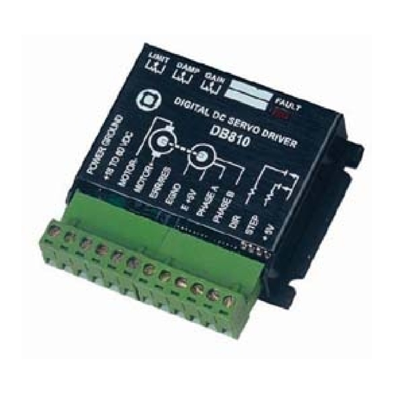
DB810
Digital DC Servo Driver
©2000 All Rights Reserved
Attention: Please read this manual carefully before using driver!
Floor 6, Block B, Yuehai Building, Nanhai Avenue, Shenzhen, China
Tel: (86)755-26471182
URL:
www.leadshine.com
雷赛智能官方代理:雷创智能科技
For
Version 1.0
Fax: (86)755-26402718
E-Mail:
sales@leadshine.com
The content in this manual has been carefully prepared and is believed to be accurate,
but no responsibility is assumed for inaccuracies.
Leadshine reserves the right to make changes without further notice to any products
herein to improve reliability, function or design. Leadshine does not assume any
liability arising out of the application or use of any product or circuit described
herein; neither does it convey any license under its patent rights of others.
Leadshine's general policy does not recommend the use of its products in life
support or aircraft applications wherein a failure or malfunction of the product may
directly threaten life or injury. According to Leadshine's terms and conditions of
sales, the user of Leadshine's products in life support or aircraft applications
assumes all risks of such use and indemnifies Leadshine against all damages.
©2000 by Leadshine Technology Company Limited.
All Rights Reserved
www.leadtronker.com
www.leadtronker.com
Advertisement
Table of Contents

Subscribe to Our Youtube Channel
Related Manuals for Leadshine DB810


Summary of Contents for Leadshine DB810
- Page 1 The content in this manual has been carefully prepared and is believed to be accurate, but no responsibility is assumed for inaccuracies. User’s Manual Leadshine reserves the right to make changes without further notice to any products herein to improve reliability, function or design. Leadshine does not assume any DB810 liability arising out of the application or use of any product or circuit described herein;...
-
Page 2: Table Of Contents
4. Servo Setup ......................5 4.1 Install Encoder....................5 4.2 Prepare Power Supply ..................5 4.3 Prepare Controller ..................6 4.4 Initialize DB810 ..................... 6 4.5 Motor connection ................... 6 5. Tuning the Servo ..................... 6 5.1 Testing the Servo .................... 6 5.2 Tuning the Servo .................... -
Page 3: Introduction, Features And Applications
AC servo systems in velocity, precision, noise, stability and some other aspects, at least as good as those of digital AC servo systems. Synchronously the price of DB810 stays at the price line of step driver, namely far lower than that of AC servo. -
Page 4: Operating Environment And Parameters
3. Connections 3.3 Typical Connections 3.1 Connector Configuration If the encoder drains less than 50mA, DB810 can supply the encoder directly, and connect it as Figure 3. If the encoder drains more than 50mA, use an external Pin Number (Term.) Function Pin Number (Term.) -
Page 5: Servo Setup
Authorized Distributor of Leadshine Technology 4.3 Prepare Controller Prepare a controller with STEP and DIR signal. 4.4 Initialize DB810 Before going on, turn the current LIMIT trimpot a quarter to half of full scale. Turn the GAIN trimpot fully off and turn the DAMP trimpot to a quarter of full scale. -
Page 6: Tuning The Servo
You can detective how the motor behaves in response to an impulse load by There are three trimpots at the side of DB810. They are GAIN, DAMP and LIMIT watching an oscilloscope, as shown in Figure 6. The easiest way to induce a separately for current setting, as shown in Figure 5. -
Page 7: Using Tips
CRITICALLY DAMPED UNDERDAMPED If at any time after that a condition occurs that causes the DB810 to “fault out”, such Figure 6: Response to an impulse load as not being able to complete a step command, the ERR/RES terminal will go to “0”, Slowly increase STEP speed until you get a picture similar to one of the three above, signaling the computer an error has occurred. -
Page 8: Reversing Default Motor Direction
The ERROR output is latched in the “ERROR” state (term. 5 = 0) by the power-on reset circuitry in the DB810. It will stay in this state indefinitely until it is cleared by applying +5V to this terminal for at least 5 seconds. - Page 9 12 months from shipping date. During the warranty before returning product for service. Please include a written description of the period, Leadshine will either, at its option, repair or replace products which proved problem along with contact name and address. Send failed product to distributor in to be defective.
Need help?
Do you have a question about the DB810 and is the answer not in the manual?
Questions and answers