Sign In
Upload
Download
Table of Contents
Contents
Add to my manuals
Delete from my manuals
Share
URL of this page:
HTML Link:
Bookmark this page
Add
Manual will be automatically added to "My Manuals"
Print this page
×
Bookmark added
×
Added to my manuals
Manuals
Brands
Leadshine Manuals
Servo Drives
HBS Series
Hardware installation manual
Leadshine HBS Series Hardware Installation Manual
Hybrid servo
Hide thumbs
1
2
Table Of Contents
3
4
5
6
7
8
9
10
11
12
13
14
15
16
17
18
19
20
21
22
page
of
22
Go
/
22
Contents
Table of Contents
Bookmarks
Table of Contents
Table of Contents
Introduction to HBS
Getting Start
Connecting Power Supply
Connecting Motor
Connecting Encoder
Connecting Control Signal
Connecting to PC Software
HBS Drive Configuration
Configuring HBS Drive by DIP Switches
Configuring HBS Drive in PC Software
Calculating Rotation Speed and Angle
Rotating the HBS Motor by Motion Controller
Rotating the HBS Motor in PC Software
Power Supply Selection
Regulated or Unregulated Power Supply
Multiple Drives
Selecting Supply Voltage
Recommended Supply Voltage
Control Signal Wiring
NPN (Sinking) Control Signal Wiring
PNP (Sourcing) Control Signal Wiring
Differential Control Signal Wiring
Output Signal Wiring
Wiring Notes
Control Signal Setup Timing
Current Control Detail
Fine Tuning
Protection Functions
Over-Current Protection
Over-Voltage Protection
Position Following Error Protection
Frequently Asked Questions
Problem Symptoms and Possible Causes
Warranty
Exclusions
Obtaining Warranty Service
Warranty Limitations
Shipping Failed Product
Contact Us
Advertisement
Quick Links
1
Table of Contents
2
Connecting Power Supply
3
Connecting Control Signal
4
Connecting to Pc Software
5
Hbs Drive Configuration
6
Configuring Hbs Drive by Dip Switches
7
Problem Symptoms and Possible Causes
Download this manual
Hardware Installation Manual
HBS Series Hybrid Servo
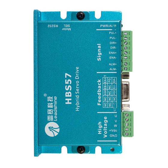
HBS57
HBS86
HBS86H
HMN_HBS_R20121128
http://www.Leadshine.com
Table of
Contents
Previous
Page
Next
Page
1
2
3
4
5
Advertisement
Table of Contents
Need help?
Do you have a question about the HBS Series and is the answer not in the manual?
Ask a question
Questions and answers
Related Manuals for Leadshine HBS Series
DC Drives Leadshine HBS86H Manual
Hybrid stepper servo drive (22 pages)
Servo Drives Leadshine HBS57 Hardware Installation Manual
Hybrid servo (22 pages)
Servo Drives Leadshine HBS86 Hardware Installation Manual
Hybrid servo (22 pages)
Servo Drives Leadshine ES-DH1208 Hardware Installation Manual
High voltage easy servo drives (27 pages)
Servo Drives Leadshine MX4660 Hardware Installation Manual
4-axis stepper drive with breakout board & i/o’s (28 pages)
Servo Drives Leadshine EL6-EC Series User Manual
Ac servo drive (290 pages)
Servo Drives Leadshine ES Series Hardware Manual
Easy servo drives (27 pages)
Servo Drives Leadshine ES2-DA808 User Manual
Vector easy servo drive (25 pages)
Servo Drives Leadshine ES-DH Series Hardware Manual
Easy servo drives (28 pages)
Servo Drives Leadshine 2ELD2-CAN Series User Manual
(122 pages)
Servo Drives Leadshine EL7-EC Series User Manual
Ac servo drive (293 pages)
Servo Drives Leadshine EL7-RS Series User Manual
Ac servo drive (314 pages)
Servo Drives Leadshine ELD2-RS Series User Manual
Dc servo drive (221 pages)
Servo Drives Leadshine EL8-EC Series User Manual
Ac servo drive (336 pages)
Servo Drives Leadshine ELD2-CAN Series User Manual
Dc servo drive (179 pages)
Servo Drives Leadshine Easy Servo Series Hardware Installation Manual
(25 pages)
This manual is also suitable for:
Hbs57
Hbs86
Hbs86h
Table of Contents
Save PDF
Print
Rename the bookmark
Delete bookmark?
Delete from my manuals?
Login
Sign In
OR
Sign in with Facebook
Sign in with Google
Upload manual
Upload from disk
Upload from URL


Need help?
Do you have a question about the HBS Series and is the answer not in the manual?
Questions and answers