Table of Contents
Advertisement
Quick Links
Advertisement
Table of Contents

Subscribe to Our Youtube Channel
Related Manuals for Leadshine 2ELD2-CAN Series


Summary of Contents for Leadshine 2ELD2-CAN Series
- Page 1 2ELD2-CAN Series Servo Drives User Manual Ver 1.0 www.leadshine.com...
- Page 2 User Manual of 2ELD2-CAN Series Servo Drives Foreword Thanks for purchasing Leadshine 2ELD2 series low-voltage DC servo drives, this instruction manual provides knowledge and attention for using this drive. Contact tech@leadshine.com for more technical service . Incorrect operation may cause unexpected accident, please read this manual carefully before using product.
-
Page 3: Introduction
User Manual of 2ELD2-CAN Series Servo Drives Installation Caution Servo Drive and Servo Motor: ⚫ Don’t install them on inflammable substance or near it to preventing fire hazard. ⚫ Avoid vibration, prohibit direct impact. ⚫ Don’t install the product while the product is damaged or incomplete. - Page 4 User Manual of 2ELD2-CAN Series Servo Drives Fault Processing Caution ⚫ The reason of fault must be figured out after alarm occurs, reset alarm signal before restart. ⚫ Keep away from machine, because of restart suddenly if the drive is powered on again after momentary...
-
Page 5: Table Of Contents
User Manual of 2ELD2-CAN Series Servo Drives Table of Contents Introduction ................................2 Chapter 1 Introduction............................8 1.1 Product Introduction ..........................8 1.1.1 Specification and feature ......................9 1.1.2 Part Numbering Information ....................... 9 1.2 Inspection of product ..........................10 Chapter 2 Installation ............................ - Page 6 User Manual of 2ELD2-CAN Series Servo Drives Chapter 5 CANopen ............................59 5.1 CAN Interface ............................59 5.2 CANopen protocol ..........................59 5.2.1 CANopen frame ........................60 5.2.2 CANopen objects ........................61 5.3 NMT ..............................61 5.3.1 NMT services ..........................63 5.3.1 NMT error control ........................
- Page 7 User Manual of 2ELD2-CAN Series Servo Drives 6.8.3 Related objects .......................... 82 6.8.4 Example of homing mode ......................82 6.8.5 Homing Method ........................83 Chapter 7 Application functions ......................... 98 7.1 Security Features ..........................98 7.1.1 STO function ..........................98 7.1.2 BRK-OFF output ........................
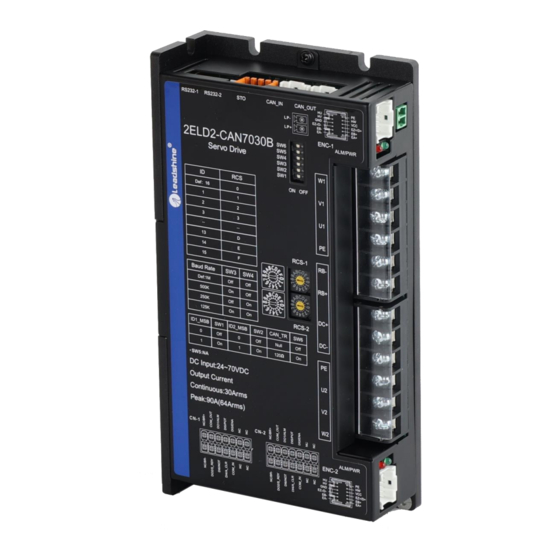
- Page 8 Chapter 1 Introduction 1.1 Product Introduction The 2ELD2 series is a new low voltage DC servo drive developed from Leadshine, dual-axis, that one 2ELD2 drive can drive two servo motors at the same time. 2ELD2 series keep the same performance of ELD2 series, relying on the special dual-axis structure, 2ELD2 series achieve less wiring, space saving, energy saving, while having a high cost performance.
-
Page 9: Chapter 1 Introduction
User Manual of 2ELD2-CAN Series Servo Drives 1.1.1 Specification and feature Specifications 2ELD2-CAN7020B 2ELD2-CAN7030B Drive model Size(mm) 194*103*41 Input main voltage(V) DC24~70 Input auxiliary power(V) DC24~70 Rated power(kw) / Axis 0.75 Rated output current(Arms) / Axis Max output current(Apeak) / Axis... -
Page 10: Specification And Feature
User Manual of 2ELD2-CAN Series Servo Drives 1.2 Inspection of product Check the following thing before using the products : a. Check if the product is damaged or not during transportation. b. Check if the servo drive & motor are complete or not. -
Page 11: Inspection Of Product
User Manual of 2ELD2-CAN Series Servo Drives Chapter 2 Installation 2.1 Storage and Installation Circumstance Table 2.1 Servo Drive, Servo Motor Storage Circumstance Requirement Item 2ELD2 series drive ELVM low voltage servo motor Temperature -20-80℃ -20-60℃ Humility Under 90%RH (free from condensation) -
Page 12: Servo Drive Installation
User Manual of 2ELD2-CAN Series Servo Drives 2.2 Servo Drive Installation Notice ⚫ Must install in control cabinet with sufficient safeguarding grade. ⚫ Must install with specified direction and intervals, and ensure good cooling condition. ⚫ Don’t install them on inflammable substance or near it to prevent fire hazard. -
Page 13: Installation Space
User Manual of 2ELD2-CAN Series Servo Drives 2.2.2 Installation Space Reserve enough surrounding space for effective cooling. Figure 2.2 Installation Space for Single Drive Figure 2.3 Installation Space for several Drives 2.3 Servo Motor Installation Notice ⚫ Don’t hold the product by the cable, motor shaft or encoder while transporting it. -
Page 14: Chapter 3 Wiring
User Manual of 2ELD2-CAN Series Servo Drives Chapter 3 Wiring Warning ⚫ The workers of participation in wiring or checking must possess sufficient ability do this job. ⚫ The wiring and check must be going with power off after five minutes. - Page 15 User Manual of 2ELD2-CAN Series Servo Drives Method for select regenerative resistance specification ⚫ Firstly, use the built-in resistance of the drive to run for a long time to see if it can meet the requirements: ensure that the drive temperature d33<60℃, the braking circuit does not alarm (Regeneration load factor d14<80), and the drive does not report overvoltage error...
-
Page 16: Wiring
User Manual of 2ELD2-CAN Series Servo Drives 3.1.2 Wiring ENC-1 RS232-1 RS232-2 CAN_IN CAN_OUT Auxiliary power VIN+ Analog VIN- input COM_IN 4.7K 4.7K 24Vdc 4.7K (Input) COM_OUT1 switch DC Power supply 24Vdc (Output) Brake output ENC-2 15 16 17 18... -
Page 17: Drive Terminals Function
User Manual of 2ELD2-CAN Series Servo Drives 3.2 Drive Terminals Function 3.2.1 Power Terminal - Axis 1 and Axis 2 Power terminal Signal Input / Output Details Output Output Power for motor 1 Output Output Input Regenerative resistor Input Output... -
Page 18: Control Signal Port -I/O - Axis 1 And Axis 2
User Manual of 2ELD2-CAN Series Servo Drives For motor with serial encoder : Encoder Signal Detail SHIELD Input Ground terminal for shielded Input +5V for encoder power supply Input Input Serial encoder signal Input Serial encoder signal 3.2.3 Control signal I/O-Port of CN1 and CN2... -
Page 19: Communication Port
User Manual of 2ELD2-CAN Series Servo Drives CN-2 Signal Detail Output Brake output, 24V/1A Output COM_OU Output Digital output signal commonality ground, 24V Digital output signal 2 ,(Servo-Ready) ,24V, 8mA Output Digital output signal 1 ,(ALARM) ,24V, 8mA Output Digital input signal 6, default value is reverse run prohibited... -
Page 20: Can Node-Id And Baud Rate Switch
User Manual of 2ELD2-CAN Series Servo Drives 3.2.6 STO Connector Signal Detail When the drive is not using the STO function, pins 1 and 2 are used to short the positive and negative terminals of SF1 and SF2 respectively. Caution: Pins 1 and 2 cannot be used to supply power to other devices. -
Page 21: I/O Interface Principle
User Manual of 2ELD2-CAN Series Servo Drives Dip Switch - Axis 1 and Axis 2 Switch Detail Axis 1 Slave -ID selection(MSB) OFF: MSB=0. Slave ID = RCS- Axis 1 ON: MSB=1. Slave ID = 16 + RCS Axis 1 Axis 2 Slave -ID selection(MSB)... - Page 22 User Manual of 2ELD2-CAN Series Servo Drives (1) 2 digital single-ended outputs DO1~DO2, support NPN and PNP connection, recommend 24V output signal. (2) If the load is inductive loads relays, etc., there must be anti-parallel freewheeling diode across the load. If the freewheeling diode is connected reversely, the servo drive is damaged.
- Page 23 User Manual of 2ELD2-CAN Series Servo Drives Assign functions to digital outputs. For the function number, please refer to the following table. Setup value Signal name Symbol Normally open Normally closed — Master control output Do not setup Alarm output...
-
Page 24: Chapter 4 Parameter
User Manual of 2ELD2-CAN Series Servo Drives Chapter 4 Parameter 4.1 Parameter List 4.1.1 Drive Parameters (Group 2000h) Parameter Number CANopen Mode Name Parameters Address Classify MFC function 2000h Pr_000 control mode setup 2001h Pr_001 real-time auto-gain tuning 2002h Pr_002... - Page 25 User Manual of 2ELD2-CAN Series Servo Drives Parameter Number CANopen Mode Name Parameters Address Classify Torque feed forward filter 2113h Pr_113 Control switching mode 2115h Pr_115 Control switching level 2117h Pr_117 Control switch hysteresis 2118h Pr_118 Gain switching time 2119h...
- Page 26 User Manual of 2ELD2-CAN Series Servo Drives Parameter Number CANopen Name Parameters Mode Address Classify Drive inhibit input setup 2504h Pr_504 Sequence at servo-off 2506h Pr_506 Main power off LV trip 2508h Pr_508 selection Main power off detection 2509h Pr_509...
-
Page 27: Manufacturer Parameters (Group 5000H)
User Manual of 2ELD2-CAN Series Servo Drives Parameter Number CANopen Name Parameters Mode Address Classify Acceleration of trial 2625h Pr_625 running Mode of trial running 2626h Pr_626 Frame error window time 2634h Pr_634 Frame error window 2635h Pr_635 Z signal duration time... - Page 28 User Manual of 2ELD2-CAN Series Servo Drives Bit6: Reserved Bit7: 82Ch Bit8: 82Dh Bit9: 832h Bit10~15: Reserved Notes: 0 invalid;1 valid 0:invalid; > 0:valid; PDO watchdog 5010 60000 Unit:ms; overtime Such as RPDO timeout alarm 818h, TPDO timeout alarm 819h Bit0:Abnormal signal protection...
-
Page 29: Device Profile Parameters (Group 6000H)
User Manual of 2ELD2-CAN Series Servo Drives Speed command r/min Actual torque 0.1% Torque command 0.1% Relative position Pulse error Internal position Pulse command Overload ratio 0.1% Discharge load rate 0.1% Inertia ratio Actual positive 0.1% torque limit value Actual negative 0.1%... - Page 30 User Manual of 2ELD2-CAN Series Servo Drives 6066 Follow error detection time 65535 Command 606B Internal command speed unit Command 606C Actual feedback speed value unit 0.1% 6071 Target torque -32768 32767 0.1% 6072 Max torque 3000 65535 0.1% 6073 Max current 0.1%...
- Page 31 User Manual of 2ELD2-CAN Series Servo Drives Command -214748 2147483 60B0 Position feedforward 3648 unit Velocity feedforward (Restricted by Command -214748 2147483 pp/pv/ 60B1 6080) unit /s 3648 0.1% 60B2 Torque feedforward -32768 32767 60B8 Touch probe control word 65535...
-
Page 32: Parameters Function
User Manual of 2ELD2-CAN Series Servo Drives 4.2 Parameters Function Here is the explanation of parameters, you can check them or modify the value using configuration software or the front panel of drive. Contact tech@leadshine.com if you need more technical service . 【 】 Class 0 Basic Setting 4.2.1... - Page 33 User Manual of 2ELD2-CAN Series Servo Drives Name Real-time Auto-gain Tuning Mode Pr0.02 — Range Unit Default Index 2002h You can set up the action mode of the real-time auto-gain tuning. Setup value Mode Varying degree of load inertia in motion invalid Real-time auto-gain tuning function is disabled.
- Page 34 User Manual of 2ELD2-CAN Series Servo Drives Name 1st Torque Limit Mode Pr0.13 Range 0~500 Unit Default Index 2013h You can set up the limit value of the motor output torque, as motor rate current %, the value can’t exceed the maximum of output current.
-
Page 35: Class 1】Gain Adjust
User Manual of 2ELD2-CAN Series Servo Drives Name CAN Node ID Mode Pr0.23* — Range 0~32767 Unit Default Index 2023h Setup the Node-ID of the slave station. Name CAN Baud rate Mode Pr0.24* — Range Unit Default Index 2024h Pr0.24 CAN baud rate (KHz) Pr0.24... - Page 36 User Manual of 2ELD2-CAN Series Servo Drives Name 1st Filter of Velocity Detection Mode Pr1.03 — Range 50~81 Unit Default Index 2103h You can set up the time constant of the low pass filter (LPF) after the speed detection, in 32 steps (50 to 81).Higher the setup, larger the time constant you can obtain so that you can decrease the motor noise,...
- Page 37 User Manual of 2ELD2-CAN Series Servo Drives 2nd Time Constant of torque Name Mode filter Pr1.09 Range 0~2500 Unit 0.01ms Default Index 2109h Position loop, velocity loop, velocity detection filter, torque command filter have their 2 pairs of gain or time constant(1st and 2nd).
- Page 38 User Manual of 2ELD2-CAN Series Servo Drives Setup Switching Gain switching condition value condition Fixed to 1st gain Fixed to the 1st gain (Pr1.00-Pr1.04) Fixed to 2nd gain Fixed to the 2nd gain (Pr1.05-Pr1.09) Reserved ⚫ Shift to the 2nd gain when the absolute value of the torque...
- Page 39 User Manual of 2ELD2-CAN Series Servo Drives Level of position control Name Mode switching Pr1.17 Mode Range 0~20000 Unit Default Index 2117h specific Unit of setting varies with switching mode. switching condition: position :encoder pulse number ; speed : r/min ; torque : % .
-
Page 40: Class 2】Vibration Suppression
User Manual of 2ELD2-CAN Series Servo Drives Pr1.37 Details Pr1.37 Details shield the Resistance discharge shield the speed out of 0x0001 0x0080 control alarm (1A1) circuit over-load error(120) shield the over-speed alarm Reserved 0x0002 0x0100 (1A0) Enable virtual IO in homing... - Page 41 User Manual of 2ELD2-CAN Series Servo Drives Set the depth of notch at the center frequency of the 1st notch filter. Notice: Higher the setup, shallower the notch depth and smaller the phase delay you can obtain. Name 2nd notch frequency Mode Pr2.04...
-
Page 42: Class 3】Velocity/ Torque Control
User Manual of 2ELD2-CAN Series Servo Drives ⚫ Set up the time constant of the1st delay filter in response to the positional command. ⚫ When a square wave command for the target speed Vc is applied, set up the time constant of the 1st delay filter as shown in the figure below. -
Page 43: Class 4】I/F Monitor Setting
User Manual of 2ELD2-CAN Series Servo Drives Deceleration time (ms)=Vc/1000 *Pr3.13 *1ms Sigmoid acceleration/deceleration Name Mode time setup Pr3.14 Range 0~1000 Unit Default Index 2314h Set S-curve time for acceleration/deceleration process when the speed command is applied. According to Pr3.12 Acceleration time setup and Pr3.13 Deceleration time setup, set up sigmoid time with time width centering the inflection point of acceleration/deceleration. - Page 44 User Manual of 2ELD2-CAN Series Servo Drives Assign functions to digital inputs. This parameter use 16 binary system to set up the values, For the function number, please refer to the following table. Setup value Signal Symbol 0x60FD(bit) Normally Normally...
- Page 45 User Manual of 2ELD2-CAN Series Servo Drives Name Positioning complete range Mode Pr4.31 Range 0~10000 Unit Default Index 2431h Setup the timing of positional deviation at which the positioning complete signal (INP1) is output. Positioning complete output Name Mode setup Pr4.32...
- Page 46 User Manual of 2ELD2-CAN Series Servo Drives The rotation speed (RPM) was used to set the output timing sequence of the zero speed detection output signal (ZSP). When the motor speed is lower than the setting speed of this parameter, zero speed detection signal (ZSP) is output.
- Page 47 User Manual of 2ELD2-CAN Series Servo Drives Set the detection timing of the speed arrival output (AT-SPEED). When the motor speed exceeds this setup value, the speed arrive output (AT-SPEED) is output. Detection is associated with 10r/min hysteresis . Name...
-
Page 48: Class 5】Extended Setup
User Manual of 2ELD2-CAN Series Servo Drives Name E-stop function Mode Pr4.43 Range Unit Default Index 2443h 0:When E-STOP is effective, the servo will forced to STOP and servo-disabled, and alarm showing(Err570). 1:When E-STOP is effective, the servo will forced to STOP and keep in servo-enable, no alarm showing. - Page 49 User Manual of 2ELD2-CAN Series Servo Drives Range 70~2000 Unit Default Index 2509h You can set up the time to detect the shutoff while the main power is kept shut off continuously. The main power off detection is invalid when you set up this to 2000.
- Page 50 User Manual of 2ELD2-CAN Series Servo Drives Set up the 2 limit value of the motor torque output The value of the parameter is limited to the maximum torque of the applicable motor. Compared with the maximum torque 6072, the actual torque limit value is smaller one...
-
Page 51: Class 6】Special Setup
User Manual of 2ELD2-CAN Series Servo Drives prevent the instantaneous jitter of capture during master and slave cooperation Torque saturation alarm detection Name Mode time Pr5.37 Range 0~5000 Unit Default Index 2537h When the duration of torque saturation reaches this value, the torque saturation signal will turn on. - Page 52 User Manual of 2ELD2-CAN Series Servo Drives Name JOG trial run command speed Mode Pr6.04 Range 0~10000 Unit r/min Default Index 2604h You can set up the command speed used for JOG trial run (velocity control). Name Position 3rd gain valid time Mode Pr6.05...
- Page 53 User Manual of 2ELD2-CAN Series Servo Drives Name Emergency stop time at alarm Mode Pr6.14 Range 0~3000 Unit Default Index 2614h Set up the time allowed to complete emergency stop in an alarm condition, exceeding this time puts this system in alarm state.
-
Page 54: Class 7】Factory Setting
User Manual of 2ELD2-CAN Series Servo Drives 2、Z signal for homing process Name Overload warning threshold Mode Pr6.62 Range 0~99 Unit Default Index 2662h Before an overload alarm,pre-alarm. upper limit of multi - turn Name Mode absolute position Pr6.63 Range... -
Page 55: Parameters Function
User Manual of 2ELD2-CAN Series Servo Drives Setup value Details Disable regenerative resistance discharge Enable reactive pump lift suppression function Enable regenerative resistance discharge Notice: Name Regenerative resistance open threshold setting Mode Pr7.32 20~90 Range Unit Default The external resistance is activated when the actual bus voltage is higher than Pr7.32 plus Pr7.33 and is deactivated when the actual bus voltage is lower than Pr7.32 minus Pr7.33... - Page 56 User Manual of 2ELD2-CAN Series Servo Drives Name Quick stop option code Structure Type INT 16 Index 605AH Access Mapping Mode Range Default PP, PV Mode 0 :Stop according to 3506h(Sequence at Servo-off),keeping Switch on disabled 1 :Stop according to 6084h(Profile deceleration),keeping Switch on disabled 2 :Stop according to 6085h(Quick stop deceleration),keeping Switch on disabled...
- Page 57 User Manual of 2ELD2-CAN Series Servo Drives Mode Profile position mode Profile velocity mode profile Torque mode Homing mode Name Actual internal position value Structure Type Dint 32 Index Encoder TPDO 6063H Access Mapping Mode Range Default - unit Actual internal position value, Encoder unit...
- Page 58 User Manual of 2ELD2-CAN Series Servo Drives Name Electronic gear denominator Structure Type Dint 32 Index Command RPDO 6091H-02 Access Mapping Mode Range Default unit Set the number of pulses required for one motor rotation. Name Number of pulses per rotation...
- Page 59 User Manual of 2ELD2-CAN Series Servo Drives Search the homing point in positive direction, deceleration point is homing switch, homing point is motor Z signal, the rising edge on the other side of homing switch must come before Z signal...
-
Page 60: Chapter 5 Canopen
User Manual of 2ELD2-CAN Series Servo Drives Chapter 5 CANopen 5.1 CAN Interface The CAN-bus(Controller Area Network-Bus)is a serial communication protocol developed by Bosch to exchange information between electronic control units on automobiles. This system makes possible to share a great amount of information between nodes and control units appended to the system, leading to a major reduction in both the number of sensors required and the quality of cables in the electrical installation. -
Page 61: Canopen Frame
User Manual of 2ELD2-CAN Series Servo Drives 5.2.1 CANopen frame CANopen protocol is based in CAN frames and uses one CAN frame for each CANopen message. There are two important parts of the frame that the user needs to modify: the arbitration field and the data field. The rest of the fields of the frame are normally automatically configured by the CAN hardware. -
Page 62: Canopen Objects
User Manual of 2ELD2-CAN Series Servo Drives 5.2.2 CANopen objects In the CANopen protocol, there are defined three main sets of objects, organized in profile areas: ⚫ Communication profile area (0x1000 to 0x1FFF): These objects relate to CANopen communication, as defined in the DS301 communication profile. - Page 63 User Manual of 2ELD2-CAN Series Servo Drives NMT state machine Transition Event After power on the system goes directly to initialization state Once initialization is completed the system enters to Pre-operational state (3), (6) Reception of Start remote node command...
-
Page 64: Nmt Services
User Manual of 2ELD2-CAN Series Servo Drives 5.3.1 NMT services The structure of each NMT service command is as follows: Data field COB-ID(hex) Number of Bytes Byte 0 Byte 1 0x000 Command specifier Node-ID The possible NMT services commands are the followings:... - Page 65 User Manual of 2ELD2-CAN Series Servo Drives The state of the heartbeat producer could be one of the followings: Communication State value(hex) State definition Boot-up Stopped Operational Pre-operational Example of NMT Node guarding: COB-ID(hex) Number of Bytes Data(hex) Description Master sends a CAN remote frame without data to node 1...
-
Page 66: Sdo
User Manual of 2ELD2-CAN Series Servo Drives Lifetime, the node assumes communication with the host is lost sends an emergency message and performs a fault reaction. Each node may have a different Lifetime. Example of NMT life guarding: COB- Number... -
Page 67: Pdo
A PDO communication parameter ⚫ A PDO mapping object 2ELD2-CAN series include 4 RPDO and 4 TPDO. Transmit PDO (TPDO) TPDOs are configured to send data from node to master after the occurrence of a trigger event or after a remote request by means of a RTR. -
Page 68: Sync
Zero or more emergency consumers may receive the emergency object. COB-ID(hex) Byte number: Emergency error codes Error registers Reserved 80+Node ID (Object 0x603F) (Object 0x1001) 2ELD2-CAN series include Emergency error codes (Object 0x603F): Emergency error codes Description 0000H 8110H CAN bus over-run 8120H CAN in error passive mode 8130H... -
Page 69: Chapter 6 Trial Run
User Manual of 2ELD2-CAN Series Servo Drives Chapter 6 Trial Run Attention ⚫ Ground the earth terminal of the motor and drive without fail. the PE terminal of drive must be reliably connected with the grounding terminal of equipment. ⚫ The drive power need with isolation transformer and power filter in order to guarantee the security and anti-jamming capability. -
Page 70: Holding Brake
User Manual of 2ELD2-CAN Series Servo Drives 6.1.2 Holding brake In applications where the motor drives the vertical axis, this brake would be used to hold and prevent the work (moving load) from falling gravity while the power to the servo is shut off. -
Page 71: Cia 402 State Machine
User Manual of 2ELD2-CAN Series Servo Drives 6.3 CIA 402 State Machine Control Main Enable power Power Disable Start Initialization Fault Disable No fault Ready Wait to switch on Disable Quick stop Stop at fault Enable Running Figue 6.1 2ELD2-CAN 402 State Machine switchover diagram The states are described in the following stable 6.2... -
Page 72: Common Functions For All Modes
User Manual of 2ELD2-CAN Series Servo Drives 6.4 Common Functions for All Modes 6.4.1 Motor Rotation Direction The Rotation Direction is defined in 607Eh. Mode Value Position 0:Rotate in the same direction as the position command mode 128:Rotate in the opposite direction as the position command Velocity 0:Rotate in the same direction as the position command... -
Page 73: Control Word
User Manual of 2ELD2-CAN Series Servo Drives The electronic gear subdivision method can be determined by modifying 6092h_01(Feed constant) The subdivision method of electronic gear can be determined by modifying 6092h_01(Feed constant) . 1、If 6092h_01(Feed constant) is not equal to 608Fh(Position encoder resolution), then: Electronic gear ratio = encoder resolution / 6092h_01 2 、If 6092h_01(Feed constant) is equal to 608Fh(Position encoder resolution), then:... -
Page 74: Status Word
User Manual of 2ELD2-CAN Series Servo Drives Change set immediately Homing New set-point operation start 6.4.5 Status Word Bit definition of Status Word 6041h. The binary representation of the statusword (6041) is as follows: Definition 15~14 Reserved 13~12 Mode specific... -
Page 75: Drive Enable
User Manual of 2ELD2-CAN Series Servo Drives Velocity Homing attained is 0 Abnormal stop Abnormal stop 6.4.6 Drive Enable This section describes how to enable the drive by control word (6040h), how to view the drive enable states by status word (6041h) Steps:... -
Page 76: Controlword In Profile Position Mode
User Manual of 2ELD2-CAN Series Servo Drives 6.5.1 Controlword in profile position mode The profile position mode uses some bits of the controlword and the statusword for mode specific purposes. The binary representation of the controlword(6040) in profile position mode is as follows:... -
Page 77: Related Objects
User Manual of 2ELD2-CAN Series Servo Drives Halt=0: Target position not reached Halt=1: Axis decelerates Target reached Halt=0: Target position reached Halt=1: Axis has velocity 0 No following error Following error Following error 6.5.3 Related objects Object Dictionary Description Setup value... -
Page 78: Profile Velocity Mode
User Manual of 2ELD2-CAN Series Servo Drives Write control word as 06H,state machine switching status 40 60 00 06 00 00 00 Switched On ->Ready to Switch On Notes: The COB-ID of step 1 (reset node) and step 2 (start node) is "0x000", and the COB-ID of the remaining steps is the address 0x600 + Node ID 6.6 Profile velocity mode... -
Page 79: Related Objects
User Manual of 2ELD2-CAN Series Servo Drives The meaning of each bit is described below, depending on its value: Name Value Description Halt=0: Target velocity not reached Halt=1: Axis decelerates Target reached Halt=0: Target velocity reached Halt=1: Axis has velocity 0... -
Page 80: Profile Torque Mode
User Manual of 2ELD2-CAN Series Servo Drives 6.7 Profile torque mode Target torque obtained from the command source is processed immediately on reception (system limits, etc.), and is delivered to the profiler afterwards. According to the predetermined parameters, the profiler generates and provides the control unit with the instantaneous target torque to be achieved. -
Page 81: Related Objects
User Manual of 2ELD2-CAN Series Servo Drives 6.7.3 Related objects Object Dictionary Description Setup value Units 6060H Mode of operation 6040H Controlword 6041H Statusword 6071H Target torque 0.1% 6087H Torque change rate 0.1% 6080H Maximum motor speed r/min 6074H Torque demand 0.1%... -
Page 82: Homing Mode
User Manual of 2ELD2-CAN Series Servo Drives 6.8 Homing mode Typically, in a homing method there are two homing speeds: the faster speed is used to find the mechanical limit, and the slower speed is used to find the index pulse. There is a compromise between search speed and homing precision, due to maximum axis deceleration and inertia. -
Page 83: Related Objects
User Manual of 2ELD2-CAN Series Servo Drives The meaning of each bit is described below, depending on its value: Homing Homing Target Description error attained reached Homing procedure is in progress Homing procedure is interrupted or not started Homing is attained but target is not reached Homing mode carried out successfully Homing error occurred;... -
Page 84: Homing Method
User Manual of 2ELD2-CAN Series Servo Drives 60 60 00 06 00 00 00 Write operation mode as 6H, homing mode 99 60 01 30 75 00 00 Write home speed-high speed as 7530H(180rpm, 10000p/r) 99 60 02 20 4e 00 00 Write home speed-low speed as 4e20H(120rpm, 10000p/r)... - Page 85 User Manual of 2ELD2-CAN Series Servo Drives Start Position Stop Position High speed Low speed 6099h-01h 6099h-02h Method -2:Search the homing point with low speed negative direction, when the torque reached then reverse the direction, when the torque is gone and Z signal coming then stop immediately.
- Page 86 User Manual of 2ELD2-CAN Series Servo Drives Method 2: If the positive limit switch is invalid, the motor will move in positive direction at high speed until the positive limit switch signal is valid. The motor stops and starts moving at low speed in negative direction. The motor stops after leaving the positive limit switch and the first encoder Z signal is valid, as shown in figure.
- Page 87 User Manual of 2ELD2-CAN Series Servo Drives If the motor stops at the homing switch position when it starts to move, the motor will move in negative direction at high speed until the homing switch invalid. Then the motor reverse the direction at low speed. The motor stops after the homing switch valid and the first encoder Z signal is valid, as shown in figure.
- Page 88 User Manual of 2ELD2-CAN Series Servo Drives 13 will be valid, indicating that the homing error and the motor will stop immediately. High speed Low speed Start Position Stop Position 6099h-01h 6099h-02h Z signal HOME-SWITCH Method 7: If the homing switch and positive limit switch is invalid, the motor will move in positive direction at high speed until the homing switch signal is valid.
- Page 89 User Manual of 2ELD2-CAN Series Servo Drives signal is valid, as shown in figure. If the homing switch and positive limit switch is invalid, the motor will move in positive direction at low speed until the positive limit switch valid. Then the motor reverse the direction at high speed until the homing switch invalid.
- Page 90 User Manual of 2ELD2-CAN Series Servo Drives High speed Low speed Start Position Stop Position 6099h-01h 6099h-02h Z signal HOME-SWITCH POT signal Method 10: If the homing switch and positive limit switch is invalid, the motor will move in positive direction at low speed.
- Page 91 User Manual of 2ELD2-CAN Series Servo Drives Method 11 If the homing switch and negative limit switch is invalid, the motor will move in negative direction at high speed until the homing switch signal is valid. Then the motor reverse the direction at low speed. The motor stops after leaving the homing switch and the first encoder Z signal is valid, as shown in figure.
- Page 92 User Manual of 2ELD2-CAN Series Servo Drives Start Position Stop Position High speed Low speed 6099h-01h 6099h-02h Z signal HOME-SWITCH NOT signa Method 13: If the homing switch and negative limit switch is invalid, the motor will move in negative direction at high speed until the homing switch invalid.Then the motor reverse the direction at low speed.The motor stops...
- Page 93 User Manual of 2ELD2-CAN Series Servo Drives Method 14: If the homing switch and positive limit switch is invalid, the motor will move in negative direction at low speed. The motor stops after the homing switch invalid and the first encoder Z signal is valid, as shown in figure.
- Page 94 User Manual of 2ELD2-CAN Series Servo Drives Method 18: This method is similar to method 2 Start Position Stop Position High speed Low speed 6099h-01h 6099h-02h POT signal Method 19: This method is similar to method 3 Start Position Stop Position...
- Page 95 User Manual of 2ELD2-CAN Series Servo Drives Method 22: This method is similar to method 6 Start Position Stop Position High speed Low speed 6099h-01h 6099h-02h HOME-SWITCH Method 23: This method is similar to method 7 Start Position Stop Potion...
- Page 96 User Manual of 2ELD2-CAN Series Servo Drives Method 25: This method is similar to method 9 Start Position Stop Position High speed Low speed 6099h-01h 6099h-02h HOME-SWITCH POT signal Method 26: This method is similar to method 10 Start Position...
- Page 97 User Manual of 2ELD2-CAN Series Servo Drives Method 28: This method is similar to method 12 Start Position Stop Position High speed Low speed 6099h-01h 6099h-02h HOME-SWITCH NOT signal Method 29: This method is similar to method 13 Start Position...
- Page 98 User Manual of 2ELD2-CAN Series Servo Drives Method 33: The motor starts to move in a negative direction and stops when the Z signal is valid. If the positive/negative limit switch signal and homing switch is valid during the homing process, the status word (6041h) bit 13 will be valid, indicating that the homing error and the motor will stop immediately.
-
Page 99: Chapter 7 Application Functions
User Manual of 2ELD2-CAN Series Servo Drives Chapter 7 Application functions 7.1 Security Features 7.1.1 STO function Description of safe torque off (STO): The safe torque off (STO) function is a safety function that shuts the motor current and turns off motor output torque by turning off the driving signal of the servo driver’s internal power transistor, when safety input... - Page 100 User Manual of 2ELD2-CAN Series Servo Drives Safety input/output signal Signal Detail When the drive is not using the STO function, pins 1 and 2 are used to short the positive and negative terminals of SF1 and SF2 respectively. Caution: Pins 1 and 2 cannot be used to supply power to other devices.
-
Page 101: Brk-Off Output
User Manual of 2ELD2-CAN Series Servo Drives 7.1.2 BRK-OFF output This function can be configured by set digital DO output functions allocation. refer to IO Pr4.10 parameter description. When the enable and time meet the set conditions, the digital output IO port can output ON. -
Page 102: Servo Stop Mode
User Manual of 2ELD2-CAN Series Servo Drives SRV_ON BRK_OFF Motor power-on Release Brake Brake Brake action Pr4.39 Velocity Notice: *1:The delay time between SRV_ON and BRK_OFF is less than 500ms; *2:Time setting in Pr4.38; *3:The delay time between the BRK_OFF signal output and the actual brake release action, which depends on the hardware characteristics of the motor brake;... -
Page 103: Two-Axis Alarm Correlation Function
User Manual of 2ELD2-CAN Series Servo Drives 7.1.5 Two-axis alarm correlation function Name Two-axis state correlation setup Mode Pr5.50 Range 0~65535 Unit Default Index 2500h-00 Description bit0 =0: The two axis “Alarm output” is not associated; bit1 =1: The two axis “Alarm output” is associated. -
Page 104: Vibration Suppression
User Manual of 2ELD2-CAN Series Servo Drives 2、Click “CCW” to make motor run to CCW direction,click “Position 1” to save the position limit 1 Click “CW” to make motor run to CW direction,click “Position 2” to save the position limit 2 Click “Run”... - Page 105 User Manual of 2ELD2-CAN Series Servo Drives 4. Upload the drive parameters, the record notch frequency saved in Pr2.07. Read the value of Pr2.07, and set this value into Pr2.01. Then reset Pr2.07 to 2000. 5. Saving parameters setting. Name...
-
Page 106: Friction Torque Compensation
User Manual of 2ELD2-CAN Series Servo Drives Set the width of notch at the center frequency of the 2nd notch filter. Notice: Higher the setup, larger the notch width you can obtain. Use with default setup in normal operation. Name... - Page 107 User Manual of 2ELD2-CAN Series Servo Drives Name Regenerative resistance control mode setting Mode Pr7.31 0~2 Range Unit Default Setup value Details Disable regenerative resistance discharge Enable reactive pump lift suppression function Enable regenerative resistance discharge Notice: Name Regenerative resistance open threshold setting Mode Pr7.32...
-
Page 108: Multi-Turn Absolute Encoder
User Manual of 2ELD2-CAN Series Servo Drives 7.6 Multi-turn absolute encoder The absolute encoder remember position, When the absolute encoder is used for the first time, user need to move to the home position, and clear the absolute position value of multiple turns through the drive to set the home position. -
Page 109: Read Absolute Position
User Manual of 2ELD2-CAN Series Servo Drives 7.6.2 Read absolute position 1、Steps: Install battery Pr0.15=1 Home process Finishing Return to home position,set Pr0.15=9 Read absolute position *Note:The newly installed encoder is not initialized and will alarm (1) Firstly, select the multi-turns absolute encoder motor, install the battery, and confirm whether the drive version supports multi-turns absolute encoder motor;... -
Page 110: Alarm
User Manual of 2ELD2-CAN Series Servo Drives 7.6.3 Alarm 1、Introductions The multi-turns absolute encoder alarm function can determine whether the absolute encoder is valid or not, such as battery under voltage or power failure, encoder fault, etc., users can judge the absolute encoder alarm through bus alarm output, IO alarm output, and drive operation panel alarm. -
Page 111: Chapter 8 Alarm And Processing
User Manual of 2ELD2-CAN Series Servo Drives Chapter 8 Alarm and Processing 8.1 Alarm List If an error has occurred, the red power LED will flash in a 5s cycle. When the fault is cleared the red power LED is always off. - Page 112 User Manual of 2ELD2-CAN Series Servo Drives Table 7.1 Error Code List 603F(hex) 1001(hex) Configuration Content Error code Error register software 2211 Over-current 2212 Over-current of intelligent power module (IPM) 3150 Current detection circuit error 3151 Current detection circuit error Power line (...
-
Page 113: Alarm Processing Method
User Manual of 2ELD2-CAN Series Servo Drives 8310 Motor over-load 8311 Drive over-load 8305 Torque saturation alarm 8401 Vibration is too large 8402 Over-speed 1 8403 Motor speed out of control 8503 Electronic gear ratio error 8611 Too large position pulse deviation... - Page 114 User Manual of 2ELD2-CAN Series Servo Drives Display: “ ”--“ ” Main Extra Error code Content: analog input circuit error Cause Confirmation Solution Analog input Wiring error Check wiring of analog input Make sure analog input wiring correctly Drive inner fault replace the drive with a new one Display: “...
- Page 115 User Manual of 2ELD2-CAN Series Servo Drives Main Extra Display: “ ” Error code Content: DC bus over-voltage Cause Confirmation Solution Vdc/GND over-voltage Check the voltage of Vdc/GND Make sure voltage of Vdc/GND in terminal proper range Inner brake circuit...
- Page 116 User Manual of 2ELD2-CAN Series Servo Drives Main Extra Display: “ ” Error code Content: drive over-heat Cause Confirmation Solution the temperature of power Check drive radiator whether Strengthen cooling conditions, promote module have exceeded the temperature is too high or...
- Page 117 User Manual of 2ELD2-CAN Series Servo Drives Main Extra Display: “ ” Error code Content: encoder line breaked Cause Confirmation Solution Encoder line disconnected check wiring if it steady or not Make encoder wiring steady Check encoder wiring if it is correct...
- Page 118 User Manual of 2ELD2-CAN Series Servo Drives Main Extra Display: “ ” Error code Content: position error over-large error Cause Confirmation Solution Unreasonable set of Check parameter Pr_014 value if it is too Enlarge the value of Pr_014 position error parameter...
- Page 119 User Manual of 2ELD2-CAN Series Servo Drives Main Extra Display: “ ” Error code Content: Motor speed out of control Cause Confirmation Solution UVW connection error Check the wiring and cable of connection error Encoder error Encoder error Replace motor Special function Set Pr1.37=4...
- Page 120 User Manual of 2ELD2-CAN Series Servo Drives Main Extra Display: “ ” Error code Content: I/F input interface function set error Cause Confirmation Solution Check the value of Pr_410, Assure the value of Pr_410, Pr_411, The input signal are assigned...
-
Page 121: Chapter 9 Product Accessory
User Manual of 2ELD2-CAN Series Servo Drives Chapter 9 Product Accessory Notice Contact tech@leadshine.com if you need more technical service. 9.1 Accessory selection Please consult our sales staff for specific selections 1. Power cable (1m,1.5m,3m,5m,7m,10m selectable) Motor Power cable Motor with –HD connector:... -
Page 122: Contact Us
User Manual of 2ELD2-CAN Series Servo Drives Contact us China Headquarters Address: 15-20/F, Block B, Nanshan I Valley, No.3157, Shahe West Road, Nanshan District, Shenzhen Leadshine America, Inc. North America Office Address: 26050 Towne Centre Dr. Foothill Ranch California United States...
Need help?
Do you have a question about the 2ELD2-CAN Series and is the answer not in the manual?
Questions and answers