Table of Contents
Advertisement
The content in this manual has been carefully prepared and is believed to be accurate,
User's Manual
but no responsibility is assumed for inaccuracies.
Leadshine reserves the right to make changes without further notice to any products
For
herein to improve reliability, function or design. Leadshine does not assume any
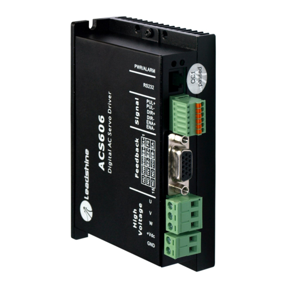
ACS606
liability arising out of the application or use of any product or circuit described
herein; neither does it convey any license under its patent rights of others.
Digital AC Servo Drive
Leadshine's general policy does not recommend the use of its products in life
support or aircraft applications wherein a failure or malfunction of the product may
Revision 1.0
directly threaten life or injury. According to Leadshine's terms and conditions of
©2009 All Rights Reserved
sales, the user of Leadshine's products in life support or aircraft applications
Attention: Please read this manual carefully before using the drive!
assumes all risks of such use and indemnifies Leadshine against all damages.
3/F, Block 2, Nanyou Tianan Industrial Park, Nanshan Dist, Shenzhen, China
©2009 by Leadshine Technology Company Limited.
Tel: (86)755-26434369
Fax: (86)755-26402718
URL:
www.leadshine.com
E-Mail:
sales@leadshine.com
All Rights Reserved
Advertisement
Table of Contents

Related Manuals for Leadshine ACS606


Summary of Contents for Leadshine ACS606
- Page 1 The content in this manual has been carefully prepared and is believed to be accurate, User’s Manual but no responsibility is assumed for inaccuracies. Leadshine reserves the right to make changes without further notice to any products herein to improve reliability, function or design. Leadshine does not assume any ACS606 liability arising out of the application or use of any product or circuit described herein;...
-
Page 2: Table Of Contents
Mechanical Specifications..................3 ProTuner Installation..................16 Elimination of Heat ....................3 Hardware Configurations before Tuning............20 Operating Environment and Parameters..............3 ProTuner for the ACS606 at Startup Window ..........21 3. Connections......................4 Introduction to ProTuner for the ACS606 ..........22 Connector Configuration..................4 Communication Setup ................23 General Information ..................4 Software Configuration before Tuning............24... -
Page 3: Introduction, Features And Applications
& tuning tools can meet different tuning environments or requirements. Encoder or Hall Error Protection..............48 The ACS606 can drive both DC brushless and AC servo motors.But it is more Position Following Error Protection............48 suitable for the DC brushless servo motors. Compare to ACS806, ACS606 has less Protection Indications.................49... -
Page 4: Applications
Particularly adapt to the applications require high speed, high precision, and low motor noise. 2. Specifications and Operating Environment Electrical Specifications (T = 25℃/77℉) ACS606 Parameters Min. Typical Max. Unit... -
Page 5: Connections
Enable input signal. This signal used for enabling/disabling the drive. High level ENA+ Enable signal input + ENA+/ENA- for enabling the drive and low level for disabling the drive. Usually left ENA- Enable signal input - UNCONNECTED (ENABLED). Tel: (86)755-26434369 Website: www.leadshine.com Tel: (86)755-26434369 Website: www.leadshine.com... -
Page 6: Control Signal Connections
Keep The ACS606 has the +5V power to supply the encoder & hall sensor. If the encoder these wires far away from the power lines. In figure 2, input circuit for these control and hall sensor drains less than 100mA, the ACS606 can supply them directly, and signals and connections to a typical motion controller is illustrated. -
Page 7: Rs232 Interface Connection
RS232 Interface Connection Figure 9: RS232 interface connection Typical Connections A typical connection of the ACS606 is shown as Figure 10. Please consult “Control Signal Connections” and “Encoder and Hall Sensor Connections” for more information about controller and encoder connections. -
Page 8: Install Encoder And Hall Sensor
Please assemble the selected module according to its factory manual. Leadshine also Prepare Controller offer BLM series DC brushless servo motors for matching the ACS606. Please use shielded cables and separate encoder signal cable from interference sources, such as Prepare a controller with pulse and direction signals. However, the ACS606 has a motor wires and power wires at least 5 cm. -
Page 9: Cable Routing
Differential signal wires should be twisted the ACS606 drive. The distance between the DC power supply of the drive and the as a pair. The combination of twisted pair wires and a differential signal significantly drive itself should be as short as possible since the cable between the two is a source adds to noise immunity. -
Page 10: Tuning The Servo
A high-gain system can produce large correcting As mentioned in previous contents, the ACS606 is a digital servo drive and its input torques when the error is very small. A high gain is required if the output is required command is PUL/DIR signal. -
Page 11: Pc Window Based Tuning Using Protuner
Introduction to ProTuner As a professional tuning tool, ProTuner has been developed specially for all Leadshine digital drives. It can be also used to configure the servo drive for many settings such as control signal modes, number of motor poles, position following error limit, default move direction, and etc. - Page 12 Set the “Shortcut Folder” in Figure 16 and continue to install the ProTuner by following Figure 17 and Figure 18. An Installation Successful window will appear if the ProTuner is installed successfully. See Figure 19. Figure 15: Installation folder settings Figure 17: Installation information summarization Tel: (86)755-26434369 Website: www.leadshine.com Tel: (86)755-26434369 Website: www.leadshine.com...
-
Page 13: Hardware Configurations Before Tuning
RJ-11 connector in which a special RS232 cable is connected to PC RS232 port. Power on the ACS606. The green LED indicator should be on and the motor shaft Before opening ProTuner to tune the ACS606, the following configuration must be should be locked if the servo system is OK. -
Page 14: Introduction To Protuner For The Acs606
LED indicator flickers. Menu Bar and Submenu Open ProTuner and the startup window appears as figure 21. For the ACS606, please select the ACS606 in AC Servo tab then click OK button. Drive Select... -
Page 15: Software Configuration Before Tuning
25. Leadshine’s ACM series servo motors. If you use the ACS606 with AC servo motors from other manufacturers, the current loop tuning may be needed. Please contact tech@leashine.com... - Page 16 Click any place of the window to zoom out. See figure 30. Large Overshoot Figure 28: Response with High Kp of current-loop(Kp = 24000) Figure 30: Drag a rectangle to zoom in Tel: (86)755-26434369 Website: www.leadshine.com Tel: (86)755-26434369 Website: www.leadshine.com...
-
Page 17: Position Loop Tuning
Feedforward gain can be added to improve tracking performance (i.e. minimize the difference between commanded and actual position). The velocity loop is disabled in current version ACS606, and it adopts Position around Current (Torque) mode. Position around Torque: This mode is most common in point-to-point applications, where actual motion between start and end point is not very critical. - Page 18 Figure 33: Position following error curve and velocity curve (Kp=2000, Ki=0 and Kd=1000) As mentioned above, the ACS606 adopts position around current (torque) mode, and It’s very easy to see from the velocity curve (Green line) that the system is under when tuning position around the current loop, a high derivative gain may be damped.
- Page 19 Figure 34: Position following error curve and velocity curve (Kp=2000, Ki=0 and Kd=3500) Figure 36: Position following error curve and velocity curve (Kp=2000, Ki=500 and Kd=7000) Figure 35: Position following error curve and velocity curve (Kp=2000, Ki=0 and Kd=7000) Tel: (86)755-26434369 Website: www.leadshine.com Tel: (86)755-26434369 Website: www.leadshine.com...
- Page 20 Figure 42 show the result after increasing Ki. From Figure 42, we can see that too much Ki will cause position curve over shoot. Figure 38: Position following error curve and velocity curve (Kp=6000, Ki=500 and Kd=7000) Tel: (86)755-26434369 Website: www.leadshine.com Tel: (86)755-26434369 Website: www.leadshine.com...
- Page 21 You can also save them to a config file on the PC harddisk then use these parameters for other drives. See detail in next chapter. Figure 41: Position following error curve and velocity curve (Kp=6000, Ki=1400 and Kd=8500) Tel: (86)755-26434369 Website: www.leadshine.com Tel: (86)755-26434369 Website: www.leadshine.com...
-
Page 22: Upload And Download Data
Upload and Download Data Download Data to EEPROM A built-in EEPROM in the ACS606 is used to save the configuration data. Every time when you finish configuration or get satisfied parameters after tuning, don’t forget to download the data to drive’s EEPROM by select Option->SaveToDrive. -
Page 23: Save Data On Harddisk
Figure 45: Upload and download window file in the list Download Data to Device When communication between ProTuner and the ACS606 is established, you can open a configuration file and download the data from the file to the drive. See figure 47 for more details. -
Page 24: Control Signal Input Mode
Interval: The interval between positive rotation and negative movement. p_ref: Position Command. This is the commanded position. Repeat_times: The repeat times of positive and negative movement. Trace Time: Trace Time. This is the trace time of the digital scope. Tel: (86)755-26434369 Website: www.leadshine.com Tel: (86)755-26434369 Website: www.leadshine.com... -
Page 25: Digital Scope Window
Erase Current Err!: Erase Current Err button. The user can clear current error(s) reset by clicking Erase Current Err! button, and all error events can be reset by by clicking this button. clicking Erase All! button. Tel: (86)755-26434369 Website: www.leadshine.com Tel: (86)755-26434369 Website: www.leadshine.com... -
Page 26: Using Tips
The user can clear all error(s) including error history by clicking this button. The ACS606 will activate a position following error if position error between command and encoder feedback exceeds the setting limit value. To set the limit 7.Using Tips value, please select Tuning->PositionLoop->P_parameter and find the Position... -
Page 27: Protection Functions
To improve reliability, the drive incorporates some built-in protection functions. The this protection too. Please check your motor connection if this protection is activated ACS606 uses one RED LED to indicate what protection has been activated. The at the startup. -
Page 28: Accessories
8. Accessories ACS606 Accessories Overview and Connections Figure 53: ACS606 accessories overview and connections with lengthening cable More Information about ACS606 Accessories ProTuner Figure 52: ACS806 accessories overview and typical connections Description PC-based configuration & tuning software. Order Standard Accessory, user can download from Leadshine website for free. - Page 29 Optional Accessory, one is enough to configure and tune multiple drives. Order CABLE-BLM-WIND Lengthening cable for power leads between the drive and Leadshine BLM Description series DC brushless servo motor. Optional Accessory, Leadshine provides 1.2m, 2.2m, 5m, 10m cable for user Order selection.
-
Page 30: Appendix
Users can select the proper length according to their needs. and workmanship for a period of 12 months from shipping date. During the warranty period, Leadshine will either, at its option, repair or replace products which proved to be defective. -
Page 31: Shipping Failed Product
Please include a written description of the problem along with contact name and address. Send failed product to distributor in your area or: Leadshine Technology Co., Ltd. Floor 3, Block 2, Tianan Industrial Park, Nanshan Dist, Shenzhen, China. Also enclose information regarding the circumstances prior to product failure.
Need help?
Do you have a question about the ACS606 and is the answer not in the manual?
Questions and answers