Table of Contents
Advertisement
Quick Links
UM12019
MCX-N5XX-EVK Board User Manual
Rev. 1 — 20 January 2024
Document information
Information
Keywords
Abstract
Content
MCX-N5XX-EVK, UM12019, MCX N54x
The NXP MCX N5XX Evaluation Kit (MCX-N5XX-EVK) board is a full-featured evaluation and
development board for application prototyping and demonstration of the MCX N54x family of
devices. This document describes the hardware for the MCX-N5XX-EVK development board.
User manual
Advertisement
Table of Contents

Related Manuals for NXP Semiconductors MCX-N5 EVK Series


Summary of Contents for NXP Semiconductors MCX-N5 EVK Series
- Page 1 UM12019 MCX-N5XX-EVK Board User Manual Rev. 1 — 20 January 2024 User manual Document information Information Content Keywords MCX-N5XX-EVK, UM12019, MCX N54x Abstract The NXP MCX N5XX Evaluation Kit (MCX-N5XX-EVK) board is a full-featured evaluation and development board for application prototyping and demonstration of the MCX N54x family of devices.
-
Page 2: Mcx-N5Xx-Evk Overview
UM12019 NXP Semiconductors MCX-N5XX-EVK Board User Manual 1 MCX-N5XX-EVK overview The NXP MCX N5XX Evaluation Kit (MCX-N5XX-EVK) board is a full-featured evaluation and development board for application prototyping and demonstration of the MCX N54X family of devices. The MCX N54X integrates a dual Arm Cortex-M33 MCU and a neural processing unit (NPU) into a single package. -
Page 3: Board Features
UM12019 NXP Semiconductors MCX-N5XX-EVK Board User Manual 1.2 Board features Table 1 describes the features of the MCX-N5XX-EVK board. Table 1. MCX-N5XX-EVK features Board feature Target MCU features used Description MCX N54X MCU The MCX N54X is based on dual high-performance Arm... -
Page 4: Board Kit Contents
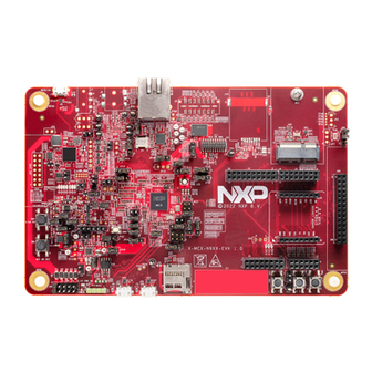
UM12019 NXP Semiconductors MCX-N5XX-EVK Board User Manual Table 1. MCX-N5XX-EVK features ...continued Board feature Target MCU features used Description Mass storage uSDHC MicroSD card connector Touch slider Touch sensing input (TSI) One Touch Slider for touch sensing detection; connects to TSI input channels through the P1_10 and P1_12 pins Debug •... - Page 5 UM12019 NXP Semiconductors MCX-N5XX-EVK Board User Manual MCX N54X processor Figure 2. MCX-N5XX-EVK top view Figure 3 shows the top-side view of the MCX-N5XX-EVK board, with connectors, push buttons, and LEDs highlighted. UM12019 All information provided in this document is subject to legal disclaimers.
- Page 6 UM12019 NXP Semiconductors MCX-N5XX-EVK Board User Manual (10 / 100 Mbit/s RJ45) (Debug and trace) (MCU-Link USB) J17 J18 (DNP) J15 (MCU-Link (External Flash) (EMV SIM) SWD) (MCU-Link (M.2) GPIO header) J2 J1 (Arduino) (DMIC EXP.) D13 D14 D8 D12 D10 D11 D9...
-
Page 7: Connectors
UM12019 NXP Semiconductors MCX-N5XX-EVK Board User Manual JP12 JP11 JP16 JP13 JP15 JP20 JP10 JP14 JP23 JP18 JP2 (DNP) JP7 JP8 JP21 JP17 JP22 JP19 JP24 JP35 JP28 JP25 JP31 JP30 JP26 JP34 JP27 JP29 JP39 JP32 JP33 JP38 JP44... -
Page 8: Jumpers
UM12019 NXP Semiconductors MCX-N5XX-EVK Board User Manual Table 2. MCX-N5XX-EVK connectors ...continued Part Connector type Description Reference section identifier RJ45 connector Shielded RJ45 connector jack with magnetic Section 2.6 built-in J9 (DNP) 2 x 14 pin header To connect external flash daughter card Section 2.5... - Page 9 UM12019 NXP Semiconductors MCX-N5XX-EVK Board User Manual Table 3. MCX-N5XX-EVK jumpers ...continued Part identifier Jumper type Description Reference section • Pin 1-2 shorted (default setting): P5V_MCU_ LINK_USB supply from MCU-Link USB micro-B connector (J5) • Pin 3-4 shorted: P5V_HDR_IN from 5 V regulator populated at 3-pin jumper (J23) •...
- Page 10 UM12019 NXP Semiconductors MCX-N5XX-EVK Board User Manual Table 3. MCX-N5XX-EVK jumpers ...continued Part identifier Jumper type Description Reference section Note: VDD_P3 must be 1.8 V for QSPI flash and SIM card interfaces. JP17 1 x 3 pin header • Pin 1-2 shorted (default setting): Port P0 pin 11 Section 2.4...
- Page 11 UM12019 NXP Semiconductors MCX-N5XX-EVK Board User Manual Table 3. MCX-N5XX-EVK jumpers ...continued Part identifier Jumper type Description Reference section JP25 1 x 2 pin header USB-to-I2C bridge enable/disable jumper Section 3.9 • Open: The USB-to-I2C bridge between MCU-Link and the target MCU is disabled •...
- Page 12 UM12019 NXP Semiconductors MCX-N5XX-EVK Board User Manual Table 3. MCX-N5XX-EVK jumpers ...continued Part identifier Jumper type Description Reference section JP38 1 x 3 pin header MCU-LINK current measurement circuit jumper Section 3.10 • Pin 1-2 shorted (default setting): MCU_PWR and MCU_PWR_SRC is sourced from P3V3 supply •...
- Page 13 UM12019 NXP Semiconductors MCX-N5XX-EVK Board User Manual Table 3. MCX-N5XX-EVK jumpers ...continued Part identifier Jumper type Description Reference section JP50 1 x 2 pin header Ethernet PHY clock input selection Section 2.6 • Pin 1-2 open: Enables crystal oscillator (Y7) to output 50 MHz clock to Ethernet PHY (LAN8741) •...
-
Page 14: Push Buttons
UM12019 NXP Semiconductors MCX-N5XX-EVK Board User Manual Table 3. MCX-N5XX-EVK jumpers ...continued Part identifier Jumper type Description Reference section • Pin 2-3 shorted: Headphone output Left / Right / MIC input /GND_SENSE 1.7 Push buttons Tactile buttons are populated on the MCX-N5XX-EVK board for human machine interaction (HMI). Each of the SW[4:2] buttons has a 0.1 µF bypass capacitor for debouncing and pads for external pull-up resistors, if desired. -
Page 15: Leds
UM12019 NXP Semiconductors MCX-N5XX-EVK Board User Manual Figure 5. Push button circuit diagram 1.8 LEDs Table 5 describes the MCX-N5XX-EVK light-emitting diodes (LEDs) that correspond to the target MCU. The board also has some MCU-Link-specific LEDs, which are described in Section 3.11. -
Page 16: Mcx-N5Xx-Evk Functional Description
UM12019 NXP Semiconductors MCX-N5XX-EVK Board User Manual The RGB LEDs are powered by the P3V3 rail. These LEDs are controlled by transistors, Q8 and Q9, which allow the LEDs to operate while being controlled by GPIOs that are powered at a voltage less than P3V3. - Page 17 UM12019 NXP Semiconductors MCX-N5XX-EVK Board User Manual A 10-pin jumper (J26) is provided on the board to make the 5 V power source selection. By default, the jumper is set to select a 5 V supply from the MCU-Link USB micro-B connector (J5). For the J26 jumper details, see Section 1.6.
- Page 18 UM12019 NXP Semiconductors MCX-N5XX-EVK Board User Manual Table 7. P3V3 power sources ...continued Part identifier Device / power source Output power supply Description • One of the sources for the VDD_P4 supply through the JP45 jumper. For details, see Section 1.6 •...
- Page 19 UM12019 NXP Semiconductors MCX-N5XX-EVK Board User Manual Table 8. P1V8 power sources ...continued Part identifier Device / power source Output power supply Description • One of the power sources for VDD_AUDIO • Power source for the MCU_PWR_SRC supply through the JP38 jumper. For details, Section 1.6...
- Page 20 UM12019 NXP Semiconductors MCX-N5XX-EVK Board User Manual Figure 10. P1V1 source selection The MCX-N5XX-EVK board supports current measurement for board power supplies through the onboard MCU-Link debug probe. For more details, see Section 3.10. Once the main power configurations are set, the target MCU power configurations must be made. The...
-
Page 21: Power Supply Configuration
UM12019 NXP Semiconductors MCX-N5XX-EVK Board User Manual SHORTING HEADER ON BOTTOM LAYER Figure 11. Power configuration jumpers 2.1.1 Power supply configuration Table 10 describes the default power jumper configuration for the MCX-N5XX-EVK board. Table 10. MCX-N5XX-EVK default power supply configuration Description JP38... -
Page 22: Dc-Dc Inductor
UM12019 NXP Semiconductors MCX-N5XX-EVK Board User Manual Table 11 describes the typical power supply configurations for DCDC operation, while Table 12 describes the typical power supply configurations for LDO operation. • MCX-N5XX-EVK power supply configurations for DCDC operation Table 11. Power supply configurations for DCDC operation... -
Page 23: Clocks
UM12019 NXP Semiconductors MCX-N5XX-EVK Board User Manual Choosing right DC-DC inductor for your target board is very important. While selecting a DC-DC inductor, look for the following specifications: • Inductor value: 1.5 µH • ESR: < 0.3 Ω • Saturation current (Isat): > 300 mA •... -
Page 24: Usb Interface
UM12019 NXP Semiconductors MCX-N5XX-EVK Board User Manual Table 13. MCX-N5XX-EVK clocks ...continued Clock Clock Destination Description generator frequency Crystal 32.7680 kHz Pin 50 (SUSCLK) of M.2 Key E card Crystal oscillator VDD is supplied by the P3V3 oscillator, Y5 connector (J12) -
Page 25: Sd Card Interface
UM12019 NXP Semiconductors MCX-N5XX-EVK Board User Manual On the MCX-N5XX-EVK board, the USB1_DM and USB1_DP signals from the MCX N54X MCU connect to the onboard USB connector (J27) directly through a common mode choke. The common mode choke is included for noise suppression on the DM / DP signals, however, pads are included to install bypass resistors for testing choke-less configurations. - Page 26 UM12019 NXP Semiconductors MCX-N5XX-EVK Board User Manual Figure 16. Micro SD card connector circuit The Port P2_[7:1] lines that are used for SDHC interface signals are also shared with the M.2 connector (J12) signals and the PWM signals on the Arduino compatible header (J3). Zero-ohm onboard resistors are used to allow the selection of signals between the SDHC card slot or the M.2 connector.
-
Page 27: Flash Memory Interface
UM12019 NXP Semiconductors MCX-N5XX-EVK Board User Manual Figure 17. uSDHC card connection selection resistors 2.5 Flash memory interface The target MCU (MCX N54X) features one flexible serial peripheral interface (FlexSPI) controller, which can support an external memory. On the MCX-N5XX-EVK board, one Quad SPI memory is provided. The flash memory VCC (VDD_FLASH) is supplied by the P1V8 rail through the JP15 jumper. - Page 28 UM12019 NXP Semiconductors MCX-N5XX-EVK Board User Manual Figure 18. FlexSPI memory and Flash daughter card circuit diagram Some of the FlexSPI signals are also multiplexed with the SAI signals for the M.2 connector. Zero-ohm onboard resistors are used to allow the selection of signals either for the QSPI flash memory or for the other connectors (flash data card connector or SAI interface of the M.2 connector).
- Page 29 UM12019 NXP Semiconductors MCX-N5XX-EVK Board User Manual Figure 19. Resistors configuration Table 16 describes the zero-ohm resistors configuration to select onboard flash memory or other board components on the flash interface lines. Table 16. Zero-ohm resistor configuration Port[pin] / Resistor Resistor configuration...
- Page 30 UM12019 NXP Semiconductors MCX-N5XX-EVK Board User Manual Table 16. Zero-ohm resistor configuration ...continued Port[pin] / Resistor Resistor configuration Description Signal • Selection B (Pin 2-3): Flash interface line connects to flash R470) to the flash chip daughter card connector select signal...
-
Page 31: Ethernet Interface
UM12019 NXP Semiconductors MCX-N5XX-EVK Board User Manual Table 16. Zero-ohm resistor configuration ...continued Port[pin] / Resistor Resistor configuration Description Signal • R968 Populated: Connects the signals from the P3_15 pin with the SAI0 interface of the M.2 connector. DNP by default. - Page 32 UM12019 NXP Semiconductors MCX-N5XX-EVK Board User Manual Two digital microphones (SPK0641HT4H-1 DMICs) are provided to supplement the audio circuit. The clock and data signals of DMICs can connect either to the MCX N54X MCU (to demonstrate the PDM capabilities) or to...
-
Page 33: Accelerometer Sensor Interface
UM12019 NXP Semiconductors MCX-N5XX-EVK Board User Manual Table 18. Audio devices ...continued Part Part name and Description Jumper settings identifier manufacturer name with a single-bit PDM Note: For jumper details, see Section 1.6. output Knowles SPK0641HT4H-1 High-performance, low- The default setting of jumpers JP10 and JP11 is power digital microphone to connect DMIC with the audio codec (DA7212). -
Page 34: I3C Interface
UM12019 NXP Semiconductors MCX-N5XX-EVK Board User Manual 2.9 I3C interface The MCX-N5XX-EVK includes one P3T1755 digital temperature sensor to demonstrate the I3C capabilities of the target MCU. This device allows for 32 I3C provisional IDs, supports the fully operating voltage of the board (1.71 V - 3.6 V), programmable overtemperature alerts, 12b resolution, and has an accuracy of ±... -
Page 35: Interface
UM12019 NXP Semiconductors MCX-N5XX-EVK Board User Manual The light sensor output is not shared with other GPIO or devices and is connected via a high-speed analog channel. The light sensor can be isolated from the MCX N54X device by cutting the shorting link SH1. - Page 36 UM12019 NXP Semiconductors MCX-N5XX-EVK Board User Manual • Ports P2 and P4 must be configured for 1.8 V operation to use this card connector. Table 20 describes the pinout of the M.2 connector (J12). Table 20. M.2 connector (J12) pinout Pin number...
- Page 37 UM12019 NXP Semiconductors MCX-N5XX-EVK Board User Manual Table 20. M.2 connector (J12) pinout ...continued Pin number Net name GPIO Potential conflict • Arduino header (J1 pin 4) UART_TXD P4_2 • mikroBUS connector (J22 pin 4) UART_CTS P4_4 PET_P0 UART_RTS P4_5 Arduino header (J1 pin 1)
-
Page 38: Emvsim Interface
UM12019 NXP Semiconductors MCX-N5XX-EVK Board User Manual Table 20. M.2 connector (J12) pinout ...continued Pin number Net name GPIO Potential conflict ALERT RESERVED PER_P1 PERST1 PER_N1 CLKREQ1 PEWAKE1 REFCLK_P1 REFCLK_N1 2.12 EMVSIM interface The MCX N54X device features two instances of the EMVSIM module, EMVSIM0 and EMVSIM1. - Page 39 UM12019 NXP Semiconductors MCX-N5XX-EVK Board User Manual Figure 25. EMVSIM connector circuit The EMVSIM connector (J10) is supported by a power switch (U48) and a voltage translator (U49). The voltage translator is required to translate the 1.8 V signals from the P3 port to the 3.3 V signals required by the EMVSIM smart cards.
-
Page 40: Arduino Compatible I/O Headers
UM12019 NXP Semiconductors MCX-N5XX-EVK Board User Manual 2.13 Arduino compatible I/O headers The MCX-N5XX-EVK provides Arduino Uno compatible headers to support the Arduino and FRDM ecosystem shield modules. These headers are dual-row headers with the outer rows supporting the Arduino compatible shields and the inner rows supporting the various FRDM shields. - Page 41 UM12019 NXP Semiconductors MCX-N5XX-EVK Board User Manual Figure 27. Arduino socket connector pinout To allow for the flexibility in the design, some of signals on the I/O headers can be swapped for other connections using zero-ohm resistors or jumpers. Table 21 describes such signals.
- Page 42 UM12019 NXP Semiconductors MCX-N5XX-EVK Board User Manual Table 22. Arduino compatible header J1 pinout ...continued Device pin / Default function Secondary function Tertiary Potential conflict number GPIO function P4_13 GPIO Motor control (ENC) FlexIO FlexIO header (J20) pin 18 P4_2 FC2_UART_TXD DAC0_OUT •...
- Page 43 UM12019 NXP Semiconductors MCX-N5XX-EVK Board User Manual Table 23. Arduino compatible header J2 pinout ...continued Device pin / Default function Secondary function Tertiary Potential conflict number GPIO function P0_25 GPIO FC1_SPI_SCK • mikroBUS socket (J19) pin 4 • MCU-Link SPI SCK...
-
Page 44: Flexio Header
UM12019 NXP Semiconductors MCX-N5XX-EVK Board User Manual Table 25. Arduino compatible header J4 pinout ...continued Device pin / Default function Secondary function Tertiary Potential conflict number GPIO function ADC0.B0 P0_4 TOUCH.S 2 P0_14 J2 pin 3 (*R949) P0_5 TOUCH.S 3 P0_22... -
Page 45: Mikrobus Headers
UM12019 NXP Semiconductors MCX-N5XX-EVK Board User Manual Table 26. FlexIO header J20 pinout ...continued Net name GPIO Function Potential conflict number FXIO0_D0/LCD_RD P0_8 Data line / LCD read M.2 connector (pin 56) LCD_TE P0_13 LCD control pin FXIO0_D16/LCD_D0 P2_8 Data line... -
Page 46: Tamper I/O Header
UM12019 NXP Semiconductors MCX-N5XX-EVK Board User Manual Table 27. J19 header pinout ...continued Pin number Net Name GPIO Functions Potential conflict P3V3 3.3 V power line Ground Table 28. J22 header pinout Pin No. Net name GPIO Functions Potential conflict P1_23 PWM output line... -
Page 47: Board Operating Conditions
UM12019 NXP Semiconductors MCX-N5XX-EVK Board User Manual • Incorrect LDO_SYS output capacitance - Boards with devices marked "PMCXN547" do not have the required 0.9 µF - 2.1 µF of capacitance. As a result, a false HVD / LVD event may occur. No other functional impacts are known. -
Page 48: Supported Debug Scenarios
UM12019 NXP Semiconductors MCX-N5XX-EVK Board User Manual Table 30. Supported MCU-Link features ...continued Feature Description Energy/power/current/voltage consumption Allows onboard measurement of current drawn by the target MCU measurement (MCUXpresso IDE only) J-Link firmware does not support this feature.) 3.3 Supported debug scenarios In the MCX-N5XX-EVK board, the MCU-Link debug probe target can be either the MCX N54X MCU or an external target compliant with MCU-Link. -
Page 49: Mcu-Link Host Driver And Utility Installation
UM12019 NXP Semiconductors MCX-N5XX-EVK Board User Manual 3.4 MCU-Link host driver and utility installation The MCU-Link debug probe is supported on Windows 10/11, MacOS X, and Ubuntu Linux platforms. The probe uses standard OS drivers. For Windows, the installation program also includes information files to provide user- friendly device names. -
Page 50: Using Mcu-Link With Development Tools
UM12019 NXP Semiconductors MCX-N5XX-EVK Board User Manual 3. Follow the instructions in the readme.txt to find and run the firmware update utilities for CMSIS-DAP or J- Link versions. 4. Disconnect the board from the host computer, open jumper JP24, and reconnect the board. The board enumerates on the host computer as a WinUSB or HID device (depending on the firmware version). -
Page 51: Connecting To A Target Through A Usb-To-Uart Bridge
UM12019 NXP Semiconductors MCX-N5XX-EVK Board User Manual 3.8 Connecting to a target through a USB-to-UART bridge The MCU-Link supports the VCOM serial port feature, which adds a serial COM port on the host computer, and connects it to the target MCU by using MCU-Link as a USB-to-UART bridge. -
Page 52: Measuring Target Mcu Power Consumption
UM12019 NXP Semiconductors MCX-N5XX-EVK Board User Manual A USB-to-I2C bridge can be used to emulate the host system / board peripherals. To use MCU-Link as a USB- to-I2C bridge, the board must be connected to the host computer through a USB cable from its J5 connector. -
Page 53: Mcu-Link Gpio Header
UM12019 NXP Semiconductors MCX-N5XX-EVK Board User Manual Table 33. MCU-Link LEDs Part LED name / MCU-Link mode identifier color Normal mode (with CMSIS-DAP Normal mode (with J- Firmware update (ISP) firmware) Link firmware) mode USB COMM / Lights up after successful USB... -
Page 54: Acronyms
UM12019 NXP Semiconductors MCX-N5XX-EVK Board User Manual Table 35. Related documentation Document Description Link / how to access MCX Nx4x Product Family Data Sheet It provides information about electrical MCXNx4x.pdf characteristics, hardware design considerations, and ordering information MCX Nx4x Reference Manual It is intended for the board-level product MCXNx4xRM.pdf... -
Page 55: Revision History
UM12019 NXP Semiconductors MCX-N5XX-EVK Board User Manual Table 36. Acronyms ...continued Term Description SDHC Secured digital host controller Serial peripheral interface Serial wire debug Serial wire debug trace output UART Universal asynchronous receiver/transmitter Universal serial bus USBSIO USB serial input/output VCOM... -
Page 56: Table Of Contents
UM12019 NXP Semiconductors MCX-N5XX-EVK Board User Manual Contents MCX-N5XX-EVK overview ....... 2 Block diagram ............2 Board features ........... 3 Board kit contents ..........4 Board pictures ........... 4 Connectors ............7 Jumpers ............. 8 Push buttons ............14 LEDs ..............15 MCX-N5XX-EVK functional description ..16 Power supplies ..........
Need help?
Do you have a question about the MCX-N5 EVK Series and is the answer not in the manual?
Questions and answers