Table of Contents
Advertisement
Quick Links
MCU-SMHMI-HDUG
Smart HMI Hardware Development User Guide
Rev. 0 — 4 November 2022
Document information
Information
Content
Keywords
MCU-SMHMI-HDUG, i.MX RT117H, EdgeReady, Smart HMI
Abstract
The Smart HMI solution is designed to provide a complete hardware and
software reference for applications that require secured face recognition and
local voice control, for example, coffee machine applications and elevator
applications
User guide
Advertisement
Table of Contents

Related Manuals for NXP Semiconductors MCU-SMHMI-HDUG


Summary of Contents for NXP Semiconductors MCU-SMHMI-HDUG
- Page 1 Document information Information Content Keywords MCU-SMHMI-HDUG, i.MX RT117H, EdgeReady, Smart HMI Abstract The Smart HMI solution is designed to provide a complete hardware and software reference for applications that require secured face recognition and local voice control, for example, coffee machine applications and elevator...
-
Page 2: Overview
MCU-SMHMI-HDUG NXP Semiconductors Smart HMI Hardware Development User Guide Overview NXP EdgeReady MCU-SMHMI solution is a Smart human machine interface (HMI) hardware and software solution for HMI projects. This solution is implemented using an NXP platform (SLN-TLHMI-IOT), which is based on NXP i.MX RT117H MCU. This solution is fully supported by NXP. -
Page 3: Related Documentation
MCU-SMHMI-HDUG NXP Semiconductors Smart HMI Hardware Development User Guide Table 1. Acronyms ...continued Acronym Meaning Real-time clock Secure digital SDHC Secure digital high capacity SDIO Secure digital input/output SDRAM Synchronous dynamic random-access memory Signal-to-noise ratio System-on-chip SRAM Static random-access memory Serial wire debug... -
Page 4: Board Features
MCU-SMHMI-HDUG NXP Semiconductors Smart HMI Hardware Development User Guide USB-C Connector DIODES INC PMIC_STBY_REQ PMIC_ON_REQ DIODE INC DIODES INC DIODES INC AP2127K-2.8 AP3429KT AP2127K-1.8 AP2127K-3.3 2V8 LDO REG 3.3V DCDC REG 1V8 LDO REG 3V3 LDO REG POWER LED Green... -
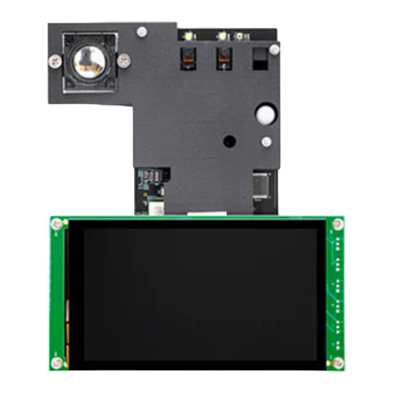
Page 5: Board Pictures
MCU-SMHMI-HDUG NXP Semiconductors Smart HMI Hardware Development User Guide Table 3. Board features ...continued Board feature Description Manufacturer and/or part number Main 3V3 DC-DC for Active mode Diodes Incorporated AP3429KT 2V8 LDO for Active mode Diodes Incorporated AP2127K-1.2 Power ICs 1V2 LDO for Active mode (not populated) Diodes Incorporated AP2127K-2.8... -
Page 6: Board Design Files
MCU-SMHMI-HDUG NXP Semiconductors Smart HMI Hardware Development User Guide White LED x2 RT117H SW3 IR LED PDM Microphone Header RT117H SW2 2W 8Ω Speaker RT117H SW1 RT117H SW0 VDD_5V MikroE Click Reserved Camera Connection Expansion Header IR Camera Module Headers... -
Page 7: I.mx Rt117H Microcontroller
MCU-SMHMI-HDUG NXP Semiconductors Smart HMI Hardware Development User Guide 2.1 i.MX RT117H microcontroller The i.MX RT117x crossover MCUs are part of the NXP EdgeVerse edge computing platform, having core frequency up to 1 GHz. This ground-breaking family combines superior computing power and multiple media capabilities with ease-of-use and real-time functionality. -
Page 8: Memories
MCU-SMHMI-HDUG NXP Semiconductors Smart HMI Hardware Development User Guide Table 7. MCU boot mode control on SLN-TLHMI-IOT board ...continued Jumper J203 setting MCU boot mode 2-3 shorted Serial Downloader The figure below shows the circuit diagram of jumper J203. VDD_3V3 BOOT_MODE[0] R263 4.7K... -
Page 9: Camera Modules
MCU-SMHMI-HDUG NXP Semiconductors Smart HMI Hardware Development User Guide on the SLN-TLHMI-IOT board. The SDRAM is connected to the i.MX RT117H MCU through its SEMC interface. The figure below shows the circuit diagram of the SDRAM. SDRAM_3V3 SEMC_A0 SEMC_A1 SEMC_A2... -
Page 10: Rgb Camera (Mipi-Csi2)
MCU-SMHMI-HDUG NXP Semiconductors Smart HMI Hardware Development User Guide 2.3.1 RGB camera (MIPI-CSI2) The SLN-TLHMI-IOT board supports an RGB camera module for supplying RGB image required for display. The camera module has a high-quality, 2 megapixel GalaxyCore GC2145 UXGA CMOS image sensor. -
Page 11: Ir Camera (Flexio)
MCU-SMHMI-HDUG NXP Semiconductors Smart HMI Hardware Development User Guide Table 10. GC2145 – i.MX RT117H signal mapping ...continued GC2145 pin name Board signal i.MX RT117H pin name (number) MDN1 MIPI_CSI_DN1 MIPI_CSI_DN1 (A13) SBCL CON_I2C6_SCL GPIO_LPSR_07 (R8) SBDA CON_I2C6_SDA GPIO_LPSR_06 (P8) GPIO_AD_13 (L12) (for... -
Page 12: Reserved Camera Connector (Parallel Csi)
MCU-SMHMI-HDUG NXP Semiconductors Smart HMI Hardware Development User Guide Table 11. GC0308 – i.MX RT117H signal mapping ...continued GC0308 pin names Board signals i.MX RT117H pin names (numbers) INCLK FLEXIO2_FLEXIO00 GPIO_AD_00 (N12) PCLK FLEXIO2_FLEXIO01 GPIO_AD_01 (R14) SBCL I2C5_SCL GPIO_LPSR_05 (N8) SBDA... -
Page 13: Leds
MCU-SMHMI-HDUG NXP Semiconductors Smart HMI Hardware Development User Guide Table 12. GC0308 – i.MX RT117H signal mapping (for reserved camera) ...continued GC0308 pin names Board signals i.MX RT117H pin names (numbers) GPIO_AD_[23:16] (J12, K12, D[0:7] CSI_D[02:09] K14, K13, L16, M16, N15, N17) 2.3.4 LEDs... - Page 14 MCU-SMHMI-HDUG NXP Semiconductors Smart HMI Hardware Development User Guide the i.MX RT117H MCU via two-lane MIPI interface. The touch panel is controlled by the i.MX RT117H MCU via its I2C5 interface and several GPIOs. The RK055AHD091 LCD display is installed on the board through a 40-pin FPC MIPI display connector (Wurth 68714014022).
-
Page 15: Wireless Connectivity
MCU-SMHMI-HDUG NXP Semiconductors Smart HMI Hardware Development User Guide VDD_3V3 Q1000 1N4148WS 10uH R72 0 MBRA160T3G NTS2101PT1G R340 R341 4.7uF 0.1UF SHDN VREF=200mV, DRIVE CURRENT 40mA UM1663S 0.1UF Backlight_CTL 100K Figure 12. UM1663S boost driver The table below shows signal mapping between the UM1663S boost driver and i.MX RT117H MCU on the SLN-TLHMI-IOT board. -
Page 16: Audio
MCU-SMHMI-HDUG NXP Semiconductors Smart HMI Hardware Development User Guide SILK = Wi-Fi_VBAT TP18 VDD_3V3 Wi-Fi_VBAT 600 OHM 22uF 10uF 0.1UF 0.1UF Wi-Fi_VBAT Wi-Fi_VBAT TP21 SILK = RXD L211 TP20 SILK = TXD 2.2uH LQM2HPN2R2MGHL TP22 SILK = RTS C347 4.7uF 0.1UF... -
Page 17: Sensors
MCU-SMHMI-HDUG NXP Semiconductors Smart HMI Hardware Development User Guide Amplifier gain is fixed and defined by R20/R23 value. Volume control has to occur in the software domain. Audio stream (similar to PWM) is provided by the i.MX RT117H MQS interface and is filtered before feeding the analog audio amplifier. Although the amplifier is connected to MQS-RIGHT/MQS_LEFT (PWM) from i.MX RT117H, the incoming signal... -
Page 18: Pir Sensor
MCU-SMHMI-HDUG NXP Semiconductors Smart HMI Hardware Development User Guide VDD_1V8 VDD_3V3 VDD_1V8 C328 C329 200PF 0.1UF C366 C365 0.1UF 0.1UF U212 M200 R297 R298 MIC_BITSTREAM00 DATA R299 MIC_CLK CLOCK VDD_1V8 SELECT NTB0102DP SPH0641LM4H-1 VDD_1V8 C344 C343 200PF 0.1UF M201 R301... -
Page 19: Power Circuitry
MCU-SMHMI-HDUG NXP Semiconductors Smart HMI Hardware Development User Guide Table 19. IRA-S210ST01 – i.MX RT117H signal mapping IRA-S210ST01 pin name Board signal i.MX RT117H pin name (number) PIR_WAKE WAKEUP (T8) 2.8 Power circuitry The SLN-TLHMI-IOT board can be powered from an external power source through a USB Type-C connector (J7). -
Page 20: User Interface Buttons
MCU-SMHMI-HDUG NXP Semiconductors Smart HMI Hardware Development User Guide the VDD_1V2 voltage. Both are controlled by PMIC_STBY_REQ from the i.MX RT117H MCU. The figure below shows the circuit diagram for the VDD_2V8 and VDD_1V2 voltage regulators. TP200 VDD_5V SILK = VDD_2V8... -
Page 21: User Led
MCU-SMHMI-HDUG NXP Semiconductors Smart HMI Hardware Development User Guide • SW1, SW2, and SW3 buttons are connected to some i.MX RT117H GPIOs. They are used in default out-of-box experience (OOBE) software to select application and MSD software update functionality. • SW4 button is connected to the POR pin of the MCU. Pressing SW4 resets the MCU. -
Page 22: Debug Interface
MCU-SMHMI-HDUG NXP Semiconductors Smart HMI Hardware Development User Guide Table 21. User RGB LED – i.MX RT117H signal mapping Board signal i.MX RT117H pin name (number) R_LED LED_RED GPIO_EMC_B2_00 (K2) G_LED LED_GREEN GPIO_EMC_B2_01 (K4) B_LED LED_BLUE GPIO_EMC_B2_02 (K3) 2.11 Debug interface The i.MX RT117H MCU supports a JTAG/SWD interface for debugging and... - Page 23 MCU-SMHMI-HDUG NXP Semiconductors Smart HMI Hardware Development User Guide VDD_3V3 VDD_5V J200 J202 SERIAL_ANALOG FLEXPWM3_PWMA02 SERIAL_RST SERIAL_INT SPI4_PCS0 LPUART12_RX SPI4_SCK LPUART12_TX_MIC_CLK SPI4_SDI I2C6_SCL SPI4_SDO I2C6_SDA R214 R246 SSM-108-F-SV SSM-108-F-SV J201 MIC_BITSTREAM02 MIC_BITSTREAM03 HDR_1X3 VDD_3V3 UART1_RX UART1_TX EXT_GPIO1 EXT_WAKE_3V3 SSM-106-F-SV Figure 24. Expansion connectors The table below shows signal mapping between the expansion connectors and i.MX...
-
Page 24: Low-Power Optimizations
MCU-SMHMI-HDUG NXP Semiconductors Smart HMI Hardware Development User Guide Table 23. Expansion connector – i.MX RT117H signal mapping ...continued Pin number Board signal i.MX RT117H pin name (number) EXT_WAKE_3V3 WAKEUP (T8) Not applicable Low-power optimizations The SLN-TLHMI-IOT board supports the Low-Power mode where only the VDD_5V, VDD_3V3_SNVS, and VDD_1V8 signals are active. -
Page 25: Revision History
MCU-SMHMI-HDUG NXP Semiconductors Smart HMI Hardware Development User Guide VDD_SNVS_ANA R338 100K PB_WAKE R339 12.0K A6HF-4102 SWITCH = 1000 VDD_SNVS_ANA R336 100K PIR_WAKE R337 12.0K R334 WL_WAKE 10.0K R335 12.0K R332 EXT_WAKE_3V3 10.0K R333 BT_WAKE 12.0K Figure 25. SW8 DIP switch Revision history The table below summarizes the revisions to this document. -
Page 26: Legal Information
NXP Semiconductors. In the event that customer uses the product for design-in and use in In no event shall NXP Semiconductors be liable for any indirect, incidental, automotive applications to automotive specifications and standards, punitive, special or consequential damages (including - without limitation - customer (a) shall use the product without NXP Semiconductors’... -
Page 27: Table Of Contents
'Legal information'. © NXP B.V. 2022. All rights reserved. For more information, please visit: http://www.nxp.com For sales office addresses, please send an email to: salesaddresses@nxp.com Date of release: 4 November 2022 Document identifier: MCU-SMHMI-HDUG...
Need help?
Do you have a question about the MCU-SMHMI-HDUG and is the answer not in the manual?
Questions and answers