Table of Contents
Advertisement
Quick Links
MCIMX93EVKUM
MCIMX93-EVK Board User Manual
Rev. 1 — 14 April 2023
Document Information
Information
Keywords
Abstract
Content
i.MX93, MCIMX93-EVK, MCIMX93EVKUM
The i.MX 93 evaluation kit (MCIMX93-EVK board) is a platform designed to show the most
commonly used features of the i.MX 93 applications processor in a small and low-cost package.
This document supports board revision A and B.
User guide
Advertisement
Table of Contents

Subscribe to Our Youtube Channel
Related Manuals for NXP Semiconductors MCIMX93-EVK


Summary of Contents for NXP Semiconductors MCIMX93-EVK
- Page 1 MCIMX93-EVK, MCIMX93EVKUM Abstract The i.MX 93 evaluation kit (MCIMX93-EVK board) is a platform designed to show the most commonly used features of the i.MX 93 applications processor in a small and low-cost package. This document supports board revision A and B.
-
Page 2: Mcimx93-Evk Overview
MCIMX93-EVK Board User Manual 1 MCIMX93-EVK overview The i.MX 93 Evaluation Kit (MCIMX93-EVK board) is a platform designed to show the most commonly used features of the i.MX 93 Applications Processor in a small and low-cost package. The MCIMX93-EVK board is an entry-level development board, which helps developers to get familiar with the processor before investing a large amount of resources in more specific designs. -
Page 3: Related Documentation
MCIMX93-EVK board. Some of the documents listed below may be available only under a non-disclosure agreement (NDA). To request access to these documents, contact your local field applications engineer (FAE) or sales representative. -
Page 4: Block Diagram
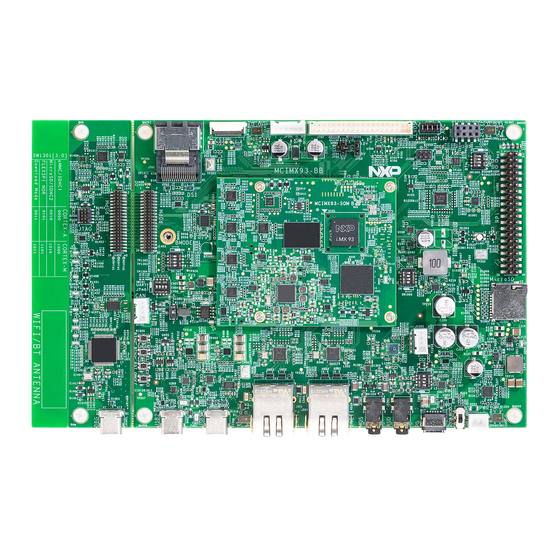
MicroSD MicroSD Figure 1. MCIMX93-EVK block diagram 1.5 Board pictures Figure 2 shows the top-side view of the MCIMX93-EVK board. MCIMX93EVKUM All information provided in this document is subject to legal disclaimers. © 2023 NXP B.V. All rights reserved. User guide Rev. - Page 5 MCIMX93-EVK Board User Manual MCIMX93-SOM MCIMX93-BB Figure 2. MCIMX93-EVK top-side view Figure 3 shows the onboard connectors on the MCIMX93-EVK board. MCIMX93EVKUM All information provided in this document is subject to legal disclaimers. © 2023 NXP B.V. All rights reserved. User guide Rev.
- Page 6 USB C PD shown in the figure is the only power supply port, and must always be supplied for system running. Figure 4 shows the onboard jumpers, switches, buttons, and LEDs available on the MCIMX93-EVK board. MCIMX93EVKUM All information provided in this document is subject to legal disclaimers.
- Page 7 SW1003 SW1002 SW1001) PWR SW (SW301) Figure 4. MCIMX93-EVK onboard jumpers, switches, buttons, and LEDs Figure 5 shows the bottom-side view of the MCIMX93-EVK board. MCIMX93EVKUM All information provided in this document is subject to legal disclaimers. © 2023 NXP B.V. All rights reserved.
-
Page 8: Board Features
NXP Semiconductors MCIMX93-EVK Board User Manual M.2 Key E (J901) Figure 5. MCIMX93-EVK bottom-side view 1.6 Board features Table 4 lists the features of MCIMX93-EVK. Table 4. MCIMX93-EVK features Board feature Target processor feature Description used Applications The i.MX 93 applications processor features dual Arm Cortex-A55 + processor Arm Cortex-M33 core speeding up to 1.7 GHz, a neural processing unit... - Page 9 MCIMX93EVKUM NXP Semiconductors MCIMX93-EVK Board User Manual Table 4. MCIMX93-EVK features ...continued Board feature Target processor feature Description used Camera interface MIPI CSI One CSI (x2 data lane) interface, J801 FPC cable connector (XF2M- 2215-1A) AR0144 camera module by default Display interface...
-
Page 10: Connectors
MCIMX93EVKUM NXP Semiconductors MCIMX93-EVK Board User Manual Table 4. MCIMX93-EVK features ...continued Board feature Target processor feature Description used Power • One USB 2.0 Type-C connector for power delivery only • PCA9451AHNY PMIC • Discrete DCDC/LDO Power monitoring Six quad-channel power monitors (PAC1934T-I) for power and energy monitoring •... -
Page 11: Jumpers
3-pin header VCC connect with VDD_3V3 by default. 1.9 User LEDs The MCIMX93-EVK board has light-emitting diodes (LEDs) to monitor system functions, such as power-on, reset, board faults. The information collected from LEDs can be used for debugging purposes. Figure 4 shows the LEDs available on the board. -
Page 12: Push Buttons
• ON: System Monitor is suspended • OFF: System Monitor is running 1.10 Push buttons Figure 4 shows the push buttons available on the board. Table 9 describes the push buttons available on MCIMX93-EVK. Table 9. MCIMX93-EVK push buttons Part identifier Switch name Description SW1001 Power button The i.MX 93 applications processor supports the use of... -
Page 13: Dip Switches
Figure 4 for switches position on the board. Four 4-bit DIP switches (SW1301, SW1005, SW1006, and SW1007) are used on the MCIMX93-EVK board for signals path selection for the below signals: • SW1301 is used for Boot Mode configuration. For more detail, see Section 2.5... -
Page 14: Mcimx93-Evk Functional Description
NXP Semiconductors MCIMX93-EVK Board User Manual 2 MCIMX93-EVK Functional Description This chapter describes the features and functions of the MCIMX93-EVK board. Note: For details of the i.MX93 MPU features, see i.MX93 Reference Manual. The chapter is divided into the following sections: •... -
Page 15: Power Supply
MCIMX93-EVK Board User Manual 2.2 Power supply The primary power supply to the MCIMX93-EVK board is VBUS_IN (12 V - 20 V) through USB Type-C PD connector (J301). One system power slider switch M096H-A020RT21A (SW301) is provided to switch ON/OFF the VBUS_IN supply on the board. - Page 16 MCIMX93EVKUM NXP Semiconductors MCIMX93-EVK Board User Manual Figure 6. MCIMX93-EVK power supply block diagram Table 11 describes different power sources available on the board. Table 11. MCIMX93-EVK power supply devices Part Manufacturing Part Power supply Specifications Description identifier part number manufacturer designator...
- Page 17 MCIMX93EVKUM NXP Semiconductors MCIMX93-EVK Board User Manual Table 11. MCIMX93-EVK power supply devices ...continued Part Manufacturing Part Power supply Specifications Description identifier part number manufacturer designator U701 PCA9451 BUCK2: • 0.6 V at 2000 mA Supplies power to: Semiconductors LPD4/x_VDDQ_0V6 • VDDQ_DDR power...
-
Page 18: Power Monitoring
For further details on the power sequence needed by the i.MX 93, refer to section "Power sequence" in i.MX 93 Applications Processor Reference Manual. 2.2.1 Power monitoring MCIMX93-EVK includes five quad-channel current monitors for power and energy monitoring. Table 12. Power monitoring devices Part identifier Manufacturing part... -
Page 19: Clocks
MCIMX93EVKUM NXP Semiconductors MCIMX93-EVK Board User Manual 2.3 Clocks MCIMX93-EVK provides all the clocks required for the processor and peripheral interfaces. Table 13 summarizes the specifications of each clock and the component that provides it. Table 13. MCIMX93-EVK clocks Part identifier Clock generator... - Page 20 MCIMX93EVKUM NXP Semiconductors MCIMX93-EVK Board User Manual Table 15. I2C devices on Base board ...continued Part Device I2C address (7- Port Speed Voltage Description identifier bit) U301 PTN5110NHQZ 0x52 MX-I2C1 1 MHz Fm+ 3.3 V USB Type-C Power (0b'10100[10]x) Delivery PHY...
-
Page 21: Boot Mode And Boot Device Configuration
1111 Test Mode On the MCIMX93-EVK board, the default boot mode is from eMMC device. The other two boot devices, the QSPI NOR Flash (M.2 QSPI card is required) and the microSD connector are on the Base Board. Set MCIMX93EVKUM All information provided in this document is subject to legal disclaimers. -
Page 22: Audio Interface
The J1201 connector is a 3.5 mm 4-pole CTIA standard audio jack. The pulse density modulated (PDM) microphone interface of the processor provides PDM/MQS support on the MCIMX93-EVK board. The TMUX1574RSVR (U1303) four-channel switch is configured through PDM/ MQS_SEL configuration signal from I/O expander (ADP5585ACPZ-00-R7, I2C Address 0x34) to output either PDM CLK/Data or MQS data. -
Page 23: Lpddr4X Dram Memory
4-pin header for connecting speaker 2.7 LPDDR4x DRAM memory MCIMX93-EVK features one 1 Gig × 16 (1 channel ×16 I/O × 1 rank) LPDDR4X SDRAM chip (MT53E1G16D1FW-046 AAT:A) for a total of 2 GB of RAM memory. The LPDDR4x DRAM memory is connected to the i.MX 93 DRAM controller. -
Page 24: Lpddr4X To Lpddr4 Migration
2.7.1 LPDDR4X to LPDDR4 migration The MCIMX93-EVK DRAM part is MT53E1G16D1FW-046 AAT:A that supports both LPDDR4X and LPDDR4 modes, however, LPDDR4X has been selected as the default option on the board. To verify LPDDR4, the two ways are as follows: •... -
Page 25: Sd Card Interface
The target processor has three ultra secured digital host controller (uSDHC) modules for SD/eMMC interface support. The uSDHC2 interface of i.MX 93 processor connects to the MicroSD card slot (J1002) on the MCIMX93-EVK board. This connector supports one 4-bit SD3.0 MicroSD card. To select it as the boot device of the board, see Section 2.5. -
Page 26: Qspi Nor Flash
CAN protocol according to the CAN with flexible data rate (CAN FD) protocol and the CAN 2.0B protocol specification. The processor supports two CAN FD controllers. On the MCIMX93-EVK board, one of the controllers is connected to the high-speed CAN transceiver TJA1057GT/3. The high-speed CAN transceiver drives CAN signals between target processor and a 4-pin header connected to its physical two-wire CAN bus. -
Page 27: Usb Interface
2.13 USB interface The i.MX 93 processor features two USB 2.0 controllers, with two integrated USB PHYs. On the MCIMX93-EVK board, one is used for the USB2.0 Type-C Port1 (J401) and the other is used for USB2.0 Type-C Port2 (J302). -
Page 28: Camera Interface
MCIMX93EVKUM NXP Semiconductors MCIMX93-EVK Board User Manual 2.14 Camera interface The i.MX 93 processor includes a mobile industry processor interface (MIPI) camera serial interface 2 (CSI-2) receiver that handles image sensor data from camera modules and supports up to 2 data lanes. The MIPI CSI-2 signals are connected to an FPC connector to which the RPI-CAM-MIPI (Agile Number: 53206) accessory card can be plugged in. -
Page 29: Lvds Interface
MCIMX93EVKUM NXP Semiconductors MCIMX93-EVK Board User Manual Table 25. DSI connector J701 pinout ...continued Pin number Signal Description Note: Signal voltage translated to 1.8 V using dual-supply translating transceiver NTS0104GU12. DSI_PWREN Enable signal from I/O expander U103 (ADP5585ACPZ, I2C address: 0x34) Note: Signal voltage translated to 1.8 V using dual-supply... -
Page 30: Expansion Connector
2.18 Expansion connector One 40-pin dual-row Pin Header connector (J1001) is provided on the MCIMX93-EVK board to support I2S, UART, I2C, and GPIO connections. The header can be used to access various pins or to plug in accessory cards, such as the 8MIC-RPI-MX8 card. - Page 31 MCIMX93EVKUM NXP Semiconductors MCIMX93-EVK Board User Manual Table 27. RPDM interface and FT4232H connections RPDM interface No. FT4232H UART channel Description 1 - JTAG Debug Channel A Remote JTAG - The A-bus of FT4232 is enumerated as JTAG (FT_JTAG). Local JTAG - Standard 10-pin JTAG header (J1405) on...
- Page 32 MCIMX93EVKUM NXP Semiconductors MCIMX93-EVK Board User Manual Table 28. 40-pin RPDM connector pinout ...continued Name Type Voltage (V) Description VDD_3V3 Output Power Backup power supply for the module Ground Ground System Control and Status Detect WDOG_B 0.8-8.0 WDOG_B from CPU to indicate CPU...
-
Page 33: Usb Debug Interface
MCIMX93EVKUM NXP Semiconductors MCIMX93-EVK Board User Manual 2.19.1 USB debug interface The i.MX 93 Applications Processor has six independent UART ports (UART1 – UART6). On the MCIMX93- EVK board, UART1 is used for Cortex-A55 core, and UART2 is used for Cortex-M33 core. A single chip USB to dual UART, JTAG, and I2C is used for UART debug and remote debug. -
Page 34: Board Errata
MCIMX93EVKUM NXP Semiconductors MCIMX93-EVK Board User Manual • JTAG_TCK (TAP Clock) • JTAG_TMS (TAP Machine State) • JTAG_TDI (TAP Data In) • JTAG_TDO (TAP Data Out) The JTAG connector (J1405) is shown in Figure 2.20 Board errata No board errata. -
Page 35: Pcb Information
NXP Semiconductors MCIMX93-EVK Board User Manual 3 PCB information The MCIMX93-EVK is composed by MCIMX93-SOM and MCIMX93-BB. Table 4 lists the dimensions of the two boards. The CPU board is made with standard 6-layer technology and the BB board is made with 8-layer technology. - Page 36 MCIMX93EVKUM NXP Semiconductors MCIMX93-EVK Board User Manual Table 32. MCIMX93-BB Board stack up information ...continued Layer Description Copper (Oz.) Generic Dielectric thickness (mil) 1080*2 Signal Dielectric Core 0.13MM 1/1 4.13 5.12 mil Dielectric 1080 RC64% 3.75 2.646 mil Signal 0.5+Plating 1.31 mil Finished: 78.74(7.874/-7.874) mil...
-
Page 37: Revision History
MCIMX93EVKUM NXP Semiconductors MCIMX93-EVK Board User Manual 4 Revision history The table below summarizes the revisions to this document. Revision history Revision Date Topic cross-reference Change description 14 April 2023 Initial public release. MCIMX93EVKUM All information provided in this document is subject to legal disclaimers. -
Page 38: Legal Information
NXP Semiconductors. In the event that customer uses the product for design-in and use in In no event shall NXP Semiconductors be liable for any indirect, incidental, automotive applications to automotive specifications and standards, punitive, special or consequential damages (including - without limitation - customer (a) shall use the product without NXP Semiconductors’... - Page 39 MCIMX93EVKUM NXP Semiconductors MCIMX93-EVK Board User Manual AMBA, Arm, Arm7, Arm7TDMI, Arm9, Arm11, Artisan, big.LITTLE, Bluetooth — the Bluetooth wordmark and logos are registered trademarks Cordio, CoreLink, CoreSight, Cortex, DesignStart, DynamIQ, Jazelle, owned by Bluetooth SIG, Inc. and any use of such marks by NXP Keil, Mali, Mbed, Mbed Enabled, NEON, POP, RealView, SecurCore, Semiconductors is under license.
-
Page 40: Table Of Contents
Connectors ............10 Jumpers ............11 User LEDs ............11 1.10 Push buttons ............12 1.11 DIP switches ............13 MCIMX93-EVK Functional Description .... 14 Processor ............14 Power supply ........... 15 2.2.1 Power monitoring ..........18 Clocks .............. 19 I2C interface ............ 19 Boot mode and boot device configuration ..21 Audio interface ..........22...
Need help?
Do you have a question about the MCIMX93-EVK and is the answer not in the manual?
Questions and answers