Advertisement
FOOTPRINT
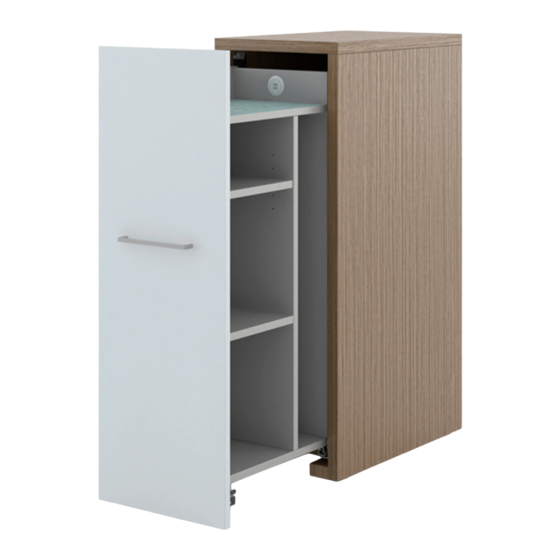
Footprint Pullout Leveling & Optional Cable Routing
Tools:
•
Cordless Drill with Phillips #2 Head Bit.
•
Socket 3/8" hex driver. For Cordless drills, 6 inch extension suggested.
•
Phillips #2 drive screw driver, 90 degree style suggested if available,
otherwise short length shaft.
•
Utility Knife, Level and Tape Measure
INSTALLATION:
WARNING
Due to the weight of the cabinet, moving it should be done with care to prevent damage. Cabinet to be
:
moved with the inner cabinet in its retracted position. Soft close slide will help keep it closed, but keep a firm grip on
cabinet during movement or use another means to keep cabinet from opening up, and potentially causing damage.
Leveling Cabinet
1. Move cabinet to its final location, and fully level rear cabinet with inner cabinet fully retracted inside rear cabinet
(Figure A). Take note of the actual dimension the front glides are adjusted outward in inches. Measure the distance
from the bottom of the door front to the floor, and note that number.
2. Unlock (if applicable) the front drawer-door and fully open cabinet and inspect for damages (Figure B). Visually
note if the cabinet has either a Salt or Pepper electrical grommet (Figure D). If not, the wiring steps that follow can
be skipped. Measure the distance from the bottom of the door front to the floor, and note that number.
3. Calculate the door front bottom gap difference. If the front was closer to the floor in the extended position, then the
difference will be used in Step 7 to extend the Inner Cabinet wheels downward.
4. Using the 90 degree Phillips #2 screw driver, loosen the screws on the top alignment wheel assembly (see Figure C)
and lower wheel down to the lowest position possible. Leave screws loose, it will be retighten later in the assembly
instructions. Cabinet must be removed with the wheel down to prevent damage to outer cabinet.
Figure A
SALT ELECTRICAL
GROMMET SHOWN
Proper product installation, in accordance with these instructions, is the responsibility of the installing agent.
If you have any questions concerning these instructions, please call Kimball Office Customer Care.
Part 3135969, Revision -
®
Figure C
SCREWS
Figure D
Assembly Instructions
Other Information Required:
•
3248081—Undermount, Soft Close Slide Ad-
justment Assembly Instructions.
1
Figure B
Advertisement
Table of Contents

Summary of Contents for Kimball FOOTPRINT
- Page 1 SCREWS Figure D SALT ELECTRICAL GROMMET SHOWN Proper product installation, in accordance with these instructions, is the responsibility of the installing agent. If you have any questions concerning these instructions, please call Kimball Office Customer Care. Part 3135969, Revision -...
- Page 2 TRACK BEFORE PUSH INNER CABINET INSIDE REAR CABINET. Proper product installation, in accordance with these instructions, is the responsibility of the installing agent. If you have any questions concerning these instructions, please call Kimball Office Customer Care. Part 3135969, Revision -...
- Page 3 Weight Here SIDE TO SIDE OFFSET DISTANCE Proper product installation, in accordance with these instructions, is the responsibility of the installing agent. If you have any questions concerning these instructions, please call Kimball Office Customer Care. Part 3135969, Revision -...
- Page 4 Roller Adjustment Wheels Figure L Figure M Proper product installation, in accordance with these instructions, is the responsibility of the installing agent. If you have any questions concerning these instructions, please call Kimball Office Customer Care. Part 3135969, Revision -...


Need help?
Do you have a question about the FOOTPRINT and is the answer not in the manual?
Questions and answers