Table of Contents
Advertisement
Quick Links
Advertisement
Table of Contents

Subscribe to Our Youtube Channel
Related Manuals for Arcteq AQ-S254


Summary of Contents for Arcteq AQ-S254
- Page 1 AQ-S254 Alarm and Indication IED Instruction manual...
-
Page 3: Table Of Contents
6.3 Real-time measurements to communication................. 71 7 Connections and applic 7 Connections and applica a tion examples tion examples....................................74 7.1 Connections of AQ-S254..................... 74 8 Construction and installa 8 Construction and installation tion ..........................................77 8.1 Construction........................77 8.2 CPU module ........................ - Page 4 9.3 Tests and environmental ....................100 10 Or 10 Ordering inf dering informa ormation tion ............................................103 11 Contact and r 11 Contact and re e f f er erence inf ence informa ormation tion....................................104 © Arcteq Relays Ltd IM00024...
- Page 5 Nothing contained in this document shall increase the liability or extend the warranty obligations of the manufacturer Arcteq Relays Ltd. The manufacturer expressly disclaims any and all liability for any damages and/or losses caused due to a failure to comply with the instructions contained herein or caused by persons who do not fulfil the aforementioned requirements.
- Page 6 A A Q Q -S254 -S254 Instruction manual Version: 2.06 Copyright Copyright © Arcteq Relays Ltd. 2022. All rights reserved. © Arcteq Relays Ltd IM00024...
-
Page 7: Document Inf
- Order codes revised. - Added double ST 100 Mbps Ethernet communication module and Double RJ45 10/100 Mbps Ethernet communication module descriptions Revision 2.02 Date 7.7.2020 Changes - A number of image descriptions improved. Revision 2.03 Date 27.8.2020 © Arcteq Relays Ltd IM00024... - Page 8 TRMS, peak-to-peak) and possible calculated measurement values (powers, impedances, angles etc.). - Improvements to many drawings and formula images. - AQ-S254 Functions included list Added: Indicator objects. - Event read mode parameter added to Modbus description. - Added inches to Dimensions and installation chapter.
-
Page 9: Version 1 Revision Notes
- Added spare part codes and compatibilities to option cards. 1.2 Version 1 revision notes Table. 1.2 - 2. Version 1 revision notes Revision 1.00 Date 15.1.2018 Changes The first revision for AQ-S254 Revision 1.01 Date 18.1.2019 Changes Added HMI display technical data © Arcteq Relays Ltd... -
Page 10: Abbr Bbre E Via Viations Tions
FFT – Fast Fourier transform FTP – File Transfer Protocol GI – General interrogation HMI – Human-machine interface HR – Holding register HV – High voltage HW – Hardware IDMT– Inverse definite minimum time IED – Intelligent electronic device © Arcteq Relays Ltd IM00024... - Page 11 SG – Setting group SOTF – Switch-on-to-fault SW – Software THD – Total harmonic distortion TRMS – True root mean square VT – Voltage transformer VTM – Voltage transformer module VTS – Voltage transformer supervision © Arcteq Relays Ltd IM00024...
-
Page 12: General
Version: 2.06 3 General The AQ-S254 alarm and indication unit is a member of the AQ-200 product line. The hardware and software are modular: the hardware modules are assembled and configured according to the application's I/O requirements and the software determines the available functions. This manual describes the specific application of the AQ-S254 alarm and indication unit. -
Page 13: Ied User Interface Erface
(hardware or software) error that affects the operation of the unit. The activation of the yellow "Start" LED and the red "Trip" LED are based on the setting the user has put in place in the software. © Arcteq Relays Ltd IM00024... -
Page 14: Configuring User Levels And Their Passwords
The different user levels and their star indicators are as follows (also, see the image below for the HMI view): • Super user (***) • Configurator (**) • Operator (*) • User ( - ) © Arcteq Relays Ltd IM00024... - Page 15 In AQ-250 frame units unlocking and locking a user level generates a time-stamped event to the event log. NOTE! Any user level with a password automatically locks itself after half an hour (30 minutes) of inactivity. © Arcteq Relays Ltd IM00024...
-
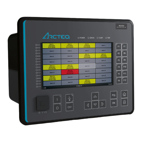
Page 16: Functions Unctions
Figure. 5.1 - 2. Front panel view Signal alarming is the main feature of AQ-S254 Alarming IEDs. The alarming unit has 128 alarms the user can set. The user defines each alarm description and activating signal. These settings are done in the Alarm settings menu ( Control →... - Page 17 GOOSE message into each of the alarms. When any of the alarms have been activated by the assigned signal, the alarm appears in the Alarms view in the relay's HMI. Figure. 5.1 - 4. Assigning alarms. © Arcteq Relays Ltd IM00024...
- Page 18 If the alarm signal's ON state has been checked in the Event Mask , an ALARM ON event is recorded with a time stamp into the event history. These alarms are also reported in the communication protocol if one is in use. © Arcteq Relays Ltd IM00024...
- Page 19 Number of columns used per page. Rows Number of rows used per page. Inactive color. Color displayed for an alarm that hasn't been activated. Active color. Color displayed for an alarm that has a signal currently active. © Arcteq Relays Ltd IM00024...
- Page 20 If alarm is cleared when signal is active, color will change to what has been set to Active cleared color in Carousel designer (orange by default). © Arcteq Relays Ltd IM00024...
- Page 21 If Zoom popup parameter is enabled in Carousel designer menu it is possible to enlarge alarms by pressing the up-arrow button. Once in zoomed mode direction arrows up, down, left and right can be used for choosing the alarm. Use Back-button to exit zoomed mode. © Arcteq Relays Ltd IM00024...
- Page 22 Alarms can be also cleared by using the CLEAR ALL ALARMS signal in the logic editor. In the example below, a physical push button activates Digital Input 1 which is connected to CLEAR ALL ALARMS. © Arcteq Relays Ltd IM00024...
- Page 23 → Logic ). Buzzer activation and deactivation AQ-S214 and AQ-S254 Alarming IEDs do not have an integrated buzzer. However, if an alarming buzzer is needed it is possible to connect an external buzzer. I is activated by one of the output relays of the IED.
- Page 24 Alarm 16 ON ALARM1 Alarm 16 OFF ALARM1 Alarm 17 ON ALARM1 Alarm 17 OFF ALARM1 Alarm 18 ON ALARM1 Alarm 18 OFF ALARM1 Alarm 19 ON ALARM1 Alarm 19 OFF ALARM1 Alarm 20 ON © Arcteq Relays Ltd IM00024...
- Page 25 Alarm 35 ON ALARM2 Alarm 35 OFF ALARM2 Alarm 36 ON ALARM2 Alarm 36 OFF ALARM2 Alarm 37 ON ALARM2 Alarm 37 OFF ALARM2 Alarm 38 ON ALARM2 Alarm 38 OFF ALARM2 Alarm 39 ON © Arcteq Relays Ltd IM00024...
- Page 26 Alarm 54 ON ALARM2 Alarm 54 OFF ALARM2 Alarm 55 ON ALARM2 Alarm 55 OFF ALARM2 Alarm 56 ON ALARM2 Alarm 56 OFF ALARM2 Alarm 57 ON ALARM2 Alarm 57 OFF ALARM2 Alarm 58 ON © Arcteq Relays Ltd IM00024...
- Page 27 Alarm 73 ON ALARM3 Alarm 73 OFF ALARM3 Alarm 74 ON ALARM3 Alarm 74 OFF ALARM3 Alarm 75 ON ALARM3 Alarm 75 OFF ALARM3 Alarm 76 ON ALARM3 Alarm 76 OFF ALARM3 Alarm 77 ON © Arcteq Relays Ltd IM00024...
- Page 28 Alarm 92 ON ALARM3 Alarm 92 OFF ALARM3 Alarm 93 ON ALARM3 Alarm 93 OFF ALARM3 Alarm 94 ON ALARM3 Alarm 94 OFF ALARM3 Alarm 95 ON ALARM3 Alarm 95 OFF ALARM3 Alarm 96 ON © Arcteq Relays Ltd IM00024...
- Page 29 Alarm 111 ON ALARM4 Alarm 111 OFF ALARM4 Alarm 112 ON ALARM4 Alarm 112 OFF ALARM4 Alarm 113 ON ALARM4 Alarm 113 OFF ALARM4 Alarm 114 ON ALARM4 Alarm 114 OFF ALARM4 Alarm 115 ON © Arcteq Relays Ltd IM00024...
-
Page 30: Control Functions
The following figure presents a simplified function block diagram of the setting group selection function. © Arcteq Relays Ltd IM00024... - Page 31 If setting groups are controlled by pulses, the setting group activated by pulse will stay active until another setting groups receives and activation signal. Figure. 5.2.1 - 13. Example sequences of group changing (control with pulse only, or with both pulses and static signals). © Arcteq Relays Ltd IM00024...
- Page 32 The selection of Setting group 1 ("SG1"). Has the highest priority input in setting group active 0: Not group control. Can be controlled with pulses or static signals. If static signal control is applied, active no other SG requests will be processed. Active © Arcteq Relays Ltd IM00024...
- Page 33 Petersen coil is connected when the network is compensated, or whether it is open when the network is unearthed. © Arcteq Relays Ltd IM00024...
- Page 34 The status of the Petersen coil controls whether Setting group 1 is active. If the coil is disconnected, Setting group 2 is active. This way, if the wire is broken for some reason, the setting group is always controlled to SG2. © Arcteq Relays Ltd IM00024...
- Page 35 A A Q Q -S254 -S254 Instruction manual Version: 2.06 Figure. 5.2.1 - 15. Setting group control – two-wire connection from Petersen coil status. © Arcteq Relays Ltd IM00024...
- Page 36 The application-controlled setting group change can also be applied entirely from the relay's internal logics. For example, the setting group change can be based on the cold load pick-up function (see the image below). © Arcteq Relays Ltd IM00024...
- Page 37 The function does not have a register. Table. 5.2.1 - 7. Event messages. Event block name Event names SG2 Enabled SG2 Disabled SG3 Enabled SG3 Disabled SG4 Enabled SG4 Disabled SG5 Enabled SG5 Disabled © Arcteq Relays Ltd IM00024...
- Page 38 Force Request Fail Force ON Force Request Fail Force OFF SG Req. Fail Lower priority Request ON SG Req. Fail Lower priority Request OFF SG1 Active ON SG1 Active OFF SG2 Active ON SG2 Active OFF © Arcteq Relays Ltd IM00024...
-
Page 39: Object Control And Monitoring
• digital input status indications (the OPEN and CLOSE status signals) • blockings (if applicable) • the OBJECT READY and SYNCHROCHECK monitor signals (if applicable). • Withdrawable cart IN and OUT status signals (if applicable). © Arcteq Relays Ltd IM00024... - Page 40 Circuit 2: Disconnector withdrawable cart is in/out status is monitored. See the next table ("Object breaker (MC) types") for a more detailed look at which functionalities each of the object types 3: Disconnector have. (GND) © Arcteq Relays Ltd IM00024...
- Page 41 Functionalities Description Breaker cart position Circuit breaker position Circuit breaker control Withdrawable circuit Object ready check before closing The monitor and control configuration of the withdrawable breaker breaker circuit breaker. Synchrochecking before closing breaker Interlocks © Arcteq Relays Ltd IM00024...
- Page 42 Determines the maximum length for a Close pulse from the output relay to the 0.02…500.00 0.02 command 0.2 s controlled object. If the object operates faster than this set time, the control pulse pulse is reset and a status change is detected. length © Arcteq Relays Ltd IM00024...
- Page 43 Blocking and interlocking can be based on any of the following: other object statuses, a software function or a digital input. The image below presents an example of an interlock application, where the closed earthing switch interlocks the circuit breaker close command. © Arcteq Relays Ltd IM00024...
- Page 44 The user can select which event messages are stored in the main event buffer: ON, OFF, or both. The function registers its operation into the last twelve (12) time-stamped registers. The events triggered by the function are recorded with a time stamp and with process data values. © Arcteq Relays Ltd IM00024...
- Page 45 Final trip ON OBJ1 Final trip OFF OBJ2 Object Intermediate OBJ2 Object Open OBJ2 Object Close OBJ2 Object Bad OBJ2 WD Intermediate OBJ2 WD Out OBJ2 WD In OBJ2 WD Bad OBJ2 Open Request ON © Arcteq Relays Ltd IM00024...
- Page 46 Open Command ON OBJ3 Open Command OFF OBJ3 Close Request ON OBJ3 Close Request OFF OBJ3 Close Command ON OBJ3 Close Command OFF OBJ3 Open Blocked ON OBJ3 Open Blocked OFF OBJ3 Close Blocked ON © Arcteq Relays Ltd IM00024...
- Page 47 Close Blocked OFF OBJ4 Object Ready OBJ4 Object Not Ready OBJ4 Sync Ok OBJ4 Sync Not Ok OBJ4 Open Command Fail OBJ4 Close Command Fail OBJ4 Final trip ON OBJ4 Final trip OFF OBJ5 Object Intermediate © Arcteq Relays Ltd IM00024...
- Page 48 Object Intermediate OBJ6 Object Open OBJ6 Object Close OBJ6 Object Bad OBJ6 WD Intermediate OBJ6 WD Out OBJ6 WD In OBJ6 WD Bad OBJ6 Open Request ON OBJ6 Open Request OFF OBJ6 Open Command ON © Arcteq Relays Ltd IM00024...
- Page 49 OBJ7 Close Request ON OBJ7 Close Request OFF OBJ7 Close Command ON OBJ7 Close Command OFF OBJ7 Open Blocked ON OBJ7 Open Blocked OFF OBJ7 Close Blocked ON OBJ7 Close Blocked OFF OBJ7 Object Ready © Arcteq Relays Ltd IM00024...
- Page 50 Object Not Ready OBJ8 Sync Ok OBJ8 Sync Not Ok OBJ8 Open Command Fail OBJ8 Close Command Fail OBJ8 Final trip ON OBJ8 Final trip OFF OBJ9 Object Intermediate OBJ9 Object Open OBJ9 Object Close © Arcteq Relays Ltd IM00024...
- Page 51 OBJ10 Object Bad OBJ10 WD Intermediate OBJ10 WD Out OBJ10 WD In OBJ10 WD Bad OBJ10 Open Request ON OBJ10 Open Request OFF OBJ10 Open Command ON OBJ10 Open Command OFF OBJ10 Close Request ON © Arcteq Relays Ltd IM00024...
-
Page 52: Indicator Object Monitoring
(2) digital inputs. Alternatively, object status monitoring can be performed with a single digital input: the input's active state and its zero state (switched to 1 with a NOT gate in the Logic editor). © Arcteq Relays Ltd IM00024... - Page 53 ON, OFF, or both. Table. 5.2.3 - 17. Event messages (instances 1-20). Event block name Event names CIN1 Intermediate CIN1 Open CIN1 Close CIN1 CIN2 Intermediate © Arcteq Relays Ltd IM00024...
- Page 54 CIN6 CIN7 Intermediate CIN7 Open CIN7 Close CIN7 CIN8 Intermediate CIN8 Open CIN8 Close CIN8 CIN9 Intermediate CIN9 Open CIN9 Close CIN9 CIN10 Intermediate CIN10 Open CIN10 Close CIN10 CIN11 Intermediate CIN11 Open CIN11 Close © Arcteq Relays Ltd IM00024...
- Page 55 CIN16 Intermediate CIN16 Open CIN16 Close CIN16 CIN17 Intermediate CIN17 Open CIN17 Close CIN17 CIN18 Intermediate CIN18 Open CIN18 Close CIN18 CIN19 Intermediate CIN19 Open CIN19 Close CIN19 CIN20 Intermediate CIN20 Open CIN20 Close CIN20 © Arcteq Relays Ltd IM00024...
-
Page 56: Milliampere Output Control
0: Currents Magnitude 1: Voltages selection for 2: Powers Defines the measurement category that is used for mA 0: Currents mA output 3: Impedance and output control. channel admittance 4: Other © Arcteq Relays Ltd IM00024... - Page 57 Table. 5.2.4 - 21. Measurement values reported by mA output cards. Name Range Step Description mA in Channel 1 Displays the measured mA value of the selected input 0.0000…24.0000mA 0.0001mA channel. mA in Channel 2 © Arcteq Relays Ltd IM00024...
-
Page 58: Programmable Control Switch
ON, OFF, or both. The function offers five (5) independent switches. Table. 5.2.5 - 23. Event messages. Event block name Event names Switch 1 ON Switch 1 OFF Switch 2 ON Switch 2 OFF Switch 3 ON Switch 3 OFF © Arcteq Relays Ltd IM00024... -
Page 59: Analog Input Scaling Curves
"ASC1...4 input out of range" signal is 1: Yes activated. -1 000 Curve1...4 input Defines the minimum input of the curve. If input is below the 000.00...1 000 0.00001 0 minimum set limit, "ASC1...4 input out of range" is activated. 000.00 © Arcteq Relays Ltd IM00024... - Page 60 If for some reason the input signal is lost, the value is fixed to the last actual measured cycle value. The value does not go down to the minimum if it has been something else at the time of the signal breaking. © Arcteq Relays Ltd IM00024...
-
Page 61: Logical Outputs
5 ("OUT5") when the circuit breaker's cart status is "In". The image above is from the logic editor and the image below from AQtivate 200. © Arcteq Relays Ltd IM00024... -
Page 62: Logical Inputs
"Pulse" mode is controlled to "1", the input will switch to status "1" and return back to "0" after 5 ms. The figure below presents the operation of a logical input in Hold mode and in Pulse mode. © Arcteq Relays Ltd IM00024... - Page 63 Table. 5.2.8 - 27. Logical input user description. Name Range Default Description User editable 1...31 Logical Description of the logical input. This description is used in several menu description LIx characters input x types for easier identification. © Arcteq Relays Ltd IM00024...
-
Page 64: Sy Y St Stem Int 6 S Em Integra Egration Tion
• Write multiple holding registers (function code 16) • Read/Write multiple registers (function code 23) The following data can be accessed using both Modbus/TCP and Modbus/RTU: • Device measurements • Device I/O • Commands • Events • Time © Arcteq Relays Ltd IM00024... -
Page 65: Modbus I/O
Defines the Modbus unit address for the selected I/O Module (A, B, or C). If this setting 0…247 address is set to "0", the selected module is not in use. Module x 0: ADAM-4018+ Selects the module type. type 1: ADAM-4015 © Arcteq Relays Ltd IM00024... -
Page 66: Iec 61850
AQ-25x frame units support both Edition 1 and 2 of IEC61850. The following services are supported by IEC 61850 in Arcteq devices: • Up to six data sets (predefined data sets can be edited with the IEC 61850 tool in AQtivate) •... -
Page 67: Goose
→ AQ-200 series → Resources). 6.1.5 GOOSE Arcteq relays support both GOOSE publisher and GOOSE subscriber. GOOSE subscriber is enabled with the "GOOSE subscriber enable" parameter at Communication → Protocols → IEC 61850/ GOOSE. The GOOSE inputs are configured using either the local HMI or the AQtivate software. -
Page 68: Iec 103
(slave) station. The IEC 103 protocol can be selected for the serial ports that are available in the device. A primary (master) station can then communicate with the Arcteq device and receive information by polling from the slave device. The transfer of disturbance recordings is not supported. -
Page 69: Dnp3
Selects the variation of the double point signal. 1: Var 2 0: Var 1 1: Var 2 Group 20 variation (CNTR) 0: Var 1 Selects the variation of the control signal. 2: Var 5 3: Var 6 © Arcteq Relays Ltd IM00024... - Page 70 Determines the data reporting deadband settings for this 0.01…5000.00V 0.01V 200V voltage deadband measurement. Angle Determines the data reporting deadband settings for this 0.1…5.0deg 0.1deg 1deg measurement deadband measurement. Integration time 0…10 000ms Displays the integration time of the protocol. © Arcteq Relays Ltd IM00024...
-
Page 71: Iec 101/104
The measurement scaling coefficients are available for the following measurements, in addition to the general measurement scaling coefficient: • Active energy • Reactive energy • Active power • Reactive power • Apparent power • Power factor • Frequency © Arcteq Relays Ltd IM00024... - Page 72 Determines the data reporting deadband settings for this 0.01…5000.00V 0.01V 200V voltage deadband measurement. Angle Determines the data reporting deadband settings for this 0.1…5.0deg 0.1deg 1deg measurement deadband measurement. Integration time 0…10 000ms Displays the integration time of the protocol. © Arcteq Relays Ltd IM00024...
-
Page 73: Spa
With the Real-time signals to communication menu the user can report to SCADA measurements that are not normally available in the communication protocols mapping. Up to eight (8) magnitudes can be selected. The recorded value can be either a per-unit value or a primary value (set by the user). © Arcteq Relays Ltd IM00024... - Page 74 Cos (φ) of three-phase powers and phase powers. cosfiL2 cosfiL3 Impedances and admittances RL12, RL23, RL31 XL12, XL23, XL31 RL1, RL2, RL3 XL1, XL2, XL3 Phase-to-phase and phase-to-neutral resistances, reactances and impedances. Z12, Z23, Z31 ZL1, ZL2, ZL3 © Arcteq Relays Ltd IM00024...
- Page 75 Displays the measured value of the selected magnitude of the selected slot. -10 000 000.000…10 000 Magnitude X 0.001 - 000.000 The unit depends on the selected magnitude (either amperes, volts, or per-unit values). © Arcteq Relays Ltd IM00024...
-
Page 76: Connections Of Aq-S254
A A Q Q -S254 -S254 Instruction manual Version: 2.06 7 Connections and application examples 7.1 Connections of AQ-S254 Figure. 7.1 - 25. AQ-S254 variant without add-on modules. © Arcteq Relays Ltd IM00024... - Page 77 A A Q Q -S254 -S254 Instruction manual Version: 2.06 Figure. 7.1 - 26. AQ-S254 variant with digital input and output modules. © Arcteq Relays Ltd IM00024...
- Page 78 A A Q Q -S254 -S254 Instruction manual Version: 2.06 Figure. 7.1 - 27. AQ-S254 application example. © Arcteq Relays Ltd IM00024...
-
Page 79: Construction And Installa
CPU, a number of inputs and outputs, and the power supply). The images below present the modules of both the non-optioned model (AQ- X254-XXXXXXX-AAAAAAAAAAAAAA AAAAAAAAAAAAAA) and the almost fully optioned model (AQ- X254-XXXXXXX-BBBBBBBBBBBCA BBBBBBBBBBBCAJ J ). Figure. 8.1 - 28. Modular construction of AQ-X254-XXXXXXX-AAAAAAAAAAAAAA © Arcteq Relays Ltd IM00024... - Page 80 In field upgrades, therefore, the add-on module must be ordered from Arcteq Relays Ltd. or its representative who can then provide the module with its corresponding unlocking code to allow the device to operate correctly once the hardware configuration has been upgraded.
- Page 81 Communication port 3 or higher, as Communication ports 1 and 2 already exist in the CPU module (which is scanned, and thus designated, first). After a communication port is detected, it is added into the device's communication space and its corresponding settings are enabled. © Arcteq Relays Ltd IM00024...
-
Page 82: Cpu Module
System fault's output relay, with a changeover contact. Pins 16 and 17 are closed when the unit has a system X1-16:17:18 fault or is powered OFF. Pins 16 and 18 are closed when the unit is powered ON and there is no system fault. © Arcteq Relays Ltd IM00024... - Page 83 (T1…Tx), it takes an additional 5 ms round. Therefore, when a digital input controls a digital output internally, it takes 0…15 milliseconds in theory and 2…13 milliseconds in practice. NOTE! The mechanical delay of the relay is no not t included in these approximations! © Arcteq Relays Ltd IM00024...
-
Page 84: Digital Input Module (Optional)
For the naming convention of the digital inputs provided by this module please refer to the chapter titled "Construction and installation". For technical details please refer to the chapter titled "Digital input module" in the "Technical data" section of this document. © Arcteq Relays Ltd IM00024... - Page 85 (NC) defines whether or not the digital input is considered activated when the digital input channel is energized. The diagram below depicts the digital input states when the input channels are energized and de- energized. © Arcteq Relays Ltd IM00024...
- Page 86 Control → Device IO → Digital inputs → Digital input voltages . Table. 8.3 - 50. Digital input channel voltage measurement. Name Range Step Description DIx Voltage now 0.000...275.000 V 0.001 V Voltage measurement of a digital input channel. © Arcteq Relays Ltd IM00024...
-
Page 87: Digital Output Module (Optional)
Table. 8.4 - 51. Digital output user description. Name Range Default Description User editable 1...31 Description of the digital output. This description is used in several menu OUTx description OUTx characters types for easier identification. © Arcteq Relays Ltd IM00024... -
Page 88: Rtd Input Module (Optional)
The RTD input module is an add-on module with eight (8) RTD input channels. Each input supports 2-wire, 3-wire and 4-wire RTD sensors. The sensor type can be selected with software for two groups, four channels each. The card supports Pt100 and Pt1000 sensors © Arcteq Relays Ltd IM00024... -
Page 89: Serial Rs-232 Communication Module (Optional)
Description • Serial-based communications • Wavelength 660 nm Serial fiber (GG/ • Compatible with 50/125 μm, 62.5/125 μm, 100/140 μm, and COM E PP/GP/PG) 200 μm Plastic-Clad Silica (PCS) fiber • Compatible with ST connectors © Arcteq Relays Ltd IM00024... -
Page 90: Lc Or Rj45 100 Mbps Ethernet Communication Module (Optional)
The option card includes two serial communication interfaces: COM E is a serial fiber interface with glass/plastic option, COM F is an RS-232 interface. 8.7 LC or RJ45 100 Mbps Ethernet communication module (optional) Figure. 8.7 - 38. LC and RJ45 100 Mbps Ethernet module connectors. © Arcteq Relays Ltd IM00024... -
Page 91: Double St 100 Mbps Ethernet Communication Module (Optional)
Two-pin connector • Duplex ST connectors • 62.5/125 μm or 50/125 μm multimode fiber • Transmitter wavelength: 1260…1360 nm (nominal: 1310 nm) ST connectors • Receiver wavelength: 1100…1600 nm • 100BASE-FX • Up to 2 km © Arcteq Relays Ltd IM00024... - Page 92 The images below present two example configurations: the first displays a ring configuration (note how the third party devices are connected in a separate ring), while the second displays a multidrop configuration. Figure. 8.8 - 40. Example of a ring configuration. © Arcteq Relays Ltd IM00024...
-
Page 93: Double Rj45 10/100 Mbps Ethernet Communication Module (Optional)
Figure. 8.8 - 41. Example of a multidrop configuration. 8.9 Double RJ45 10/100 Mbps Ethernet communication module (optional) Figure. 8.9 - 42. Double RJ-45 10/100 Mbps Ethernet communication module. Connector Description • IRIG-B input Two-pin connector © Arcteq Relays Ltd IM00024... -
Page 94: Dimensions And Installation
(½) of the rack's width, meaning that a total of two devices can be installed to the same rack next to one another. The figures below describe the device dimensions (first figure), the device installation (second), and the panel cutout dimensions and device spacing (third). © Arcteq Relays Ltd IM00024... - Page 95 A A Q Q -S254 -S254 Instruction manual Version: 2.06 Figure. 8.10 - 44. Device dimensions. Figure. 8.10 - 45. Device installation. © Arcteq Relays Ltd IM00024...
- Page 96 A A Q Q -S254 -S254 Instruction manual Version: 2.06 Figure. 8.10 - 46. Panel cut-out and spacing of the IED. © Arcteq Relays Ltd IM00024...
-
Page 97: Hardware
Solid or stranded wire 2.5 mm Maximum wire diameter Other Minimum recommended fuse rating MCB C2 9.1.1.2 CPU communication ports Table. 9.1.1.2 - 54. Front panel local communication port. Port Port media Copper Ethernet RJ-45 © Arcteq Relays Ltd IM00024... -
Page 98: Cpu Digital Inputs
9.1.1.3 CPU digital inputs Table. 9.1.1.3 - 57. CPU model-isolated digital inputs, with thresholds defined by order code. Rated values Rated auxiliary voltage 265 V (AC/DC) Nominal voltage Order code defined: 24, 110, 220 V (AC/DC) © Arcteq Relays Ltd IM00024... -
Page 99: Cpu Digital Outputs
Make and carry 3 s 15 A Breaking capacity, DC (L/R = 40 ms) at 48 VDC at 110 VDC 0.4 A at 220 VDC 0.2 A Control rate 5 ms Settings Polarity Software settable: Normally On/Normally Off © Arcteq Relays Ltd IM00024... -
Page 100: Option Cards
0.4 A at 220 VDC 0.2 A Control rate 5 ms Settings Polarity Software settable: Normally On/Normally Off Terminal block connection Terminal block Phoenix Contact MSTB 2,5/5-ST-5,08 Solid or stranded wire 2.5 mm Maximum wire diameter © Arcteq Relays Ltd IM00024... - Page 101 Table. 9.1.3 - 65. Technical data for the HMI TFT display. Dimensions and resolution Number of dots/resolution 800 x 480 Size 154.08 × 85.92 mm (6.06 × 3.38 in) Display Type of display Color RGB color © Arcteq Relays Ltd IM00024...
- Page 102 Object control during auto-reclosing See the technical sheet for the auto-reclosing function. 9.2.2 Monitoring functions 9.3 Tests and environmental Electrical environment compatibility Table. 9.3 - 68. Disturbance tests. All tests CE-approved and tested according to EN 60255-26 Emissions © Arcteq Relays Ltd IM00024...
- Page 103 Operational: +25…+55 °C, 93…97 % (RH), 12+12h Dry heat Storage: +70 °C, 16 h EN 60255-1, IEC 60068-2-2 Operational: +55 °C, 16 h Cold test Storage: –40 °C, 16 h EN 60255-1, IEC 60068-2-1 Operational: –20 °C, 16 h © Arcteq Relays Ltd IM00024...
- Page 104 Height: 208 mm Dimensions Width: 257 mm (½ rack) Depth: 165 mm (no cards or connectors) Weight 1.5 kg With packaging (gross) Height: 250 mm Dimensions Width: 343 mm Depth: 256 mm Weight 2.0 kg © Arcteq Relays Ltd IM00024...
- Page 105 ADAM-4018+- External 8-ch Thermocouple mA Input module, pre- Requires an external power Advanced Co. configured module Ltd. AQX121 Raising frame 120mm Arcteq Ltd. AQX122 Raising frame 40mm Arcteq Ltd. AQX098 Wall mounting bracket Arcteq Ltd. © Arcteq Relays Ltd IM00024...
- Page 106 Arcteq Relays Ltd. Visiting and postal address Kvartsikatu 2 A 1 65300 Vaasa, Finland Contacts Phone: +358 10 3221 370 Website: arcteq.fi Technical support: support.arcteq.fi +358 10 3221 388 (EET 9:00 – 17.00) E-mail (sales): sales@arcteq.fi © Arcteq Relays Ltd IM00024...
Need help?
Do you have a question about the AQ-S254 and is the answer not in the manual?
Questions and answers