Table of Contents
Advertisement
Quick Links
Safety warnings
Attention:
• Electrical equipment must be installed and
fitted by qualified electricians only and in
strict observance of the relevant accident
prevention regulations.
• Failure to observe any of the current regula-
tions and the instructions set out below may
result in fire and in other hazards.
1. Overview
The present instructions are applicable to Berker
touch sensors with room temperature controller
and display (in the following text referred to as "RT
touch sensor") in 2-key, 3-key and 5-key design.
1.1 Functional description
The RT touch sensor combines the functions of
touch sensor, room temperature controller and
room temperature timer clock in the same hous-
ing, thus permitting the control of many different
functions in a building. The touch sensor functions
are dependent on programming and on the other
devices in your EIB installation.
The RT touch sensor is adapted to your individual
needs and to the functions of the building. Func-
tioning and operation of the touch sensor should be
agreed between the user and the electrical fitter.
Display functions
• Room temperature and/or outside temperature
and reference temperature value
• Simple and fast adaption of the room
temperature
• Day of the week and time of day
(only with EIB DCF77 clock)
• Adaptation of the reference temperature values
for different operating modes
• Local programming of the room temperature
timer clock
Function keys
• Switching and dimming of lighting
• Opening/closing and positioning of blinds
and shutters
• Recalling and storing of 8 light scenes
• Transmitting temperature and brightness
values
• Defining operating modes for the room tem-
perature controller
• Activating/deactivating the room temperature
timer clock
LED functions
• Status display or display of pressed key
• LED on or off
1.2 Control and display elements
The controls of the device are discussed below
based on the 3-key model.
The control elements are arranged horizontally and
consist of a right and a left key.
Control element overview:
1
Display keys
- setting of values
(e.g. reference temperature value)
- programming of the room temperature
timer clock (see chapter 4)
2...4 Function keys
- pushbutton and rocker-button functions
(switching, dimming, shutter, etc.)
5
Operation LED (white)
- indication of ready-for-operation state
(programmable)
6
Status LED (red)
- display of status or of pressed key
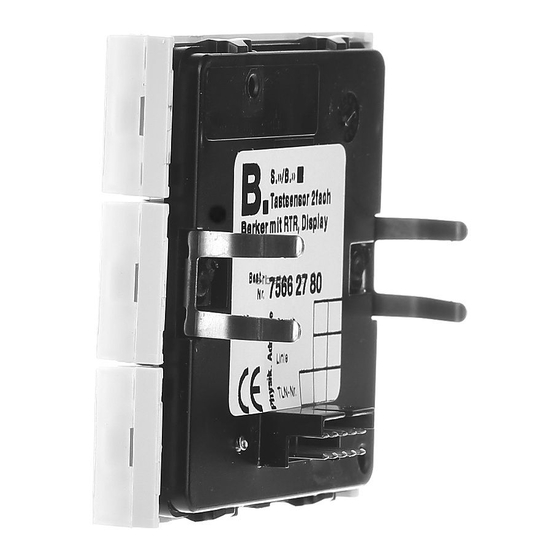
Touch sensor with room
temperature control
and display
2-key
Order no. 7566 27 xx
3-key
Order no. 7566 37 xx
5-key
Order no. 7566 57 xx
Operating- and Fitting Instructions
Contents
1.
Overview ............................................... 1
1.1
Functional description ........................... 1
1.2
Control and display elements ................. 1
2.
Operation .............................................. 2
2.1
Function keys ......................................... 2
2.2
room temperature controller .................. 2
2.3
Display symbols ..................................... 2
2.4
Basic screen .......................................... 2
2.5
Changing the room temperature ............ 2
2.6
Main menu ............................................. 3
3.
3.1
Operating modes ................................... 3
3.2
Changing the operating mode ............... 3
3.3
Enlarged operating modes ..................... 3
3.4
4.
Room temperature timer clock .......... 4
4.1
timer clock ............................................. 4
4.2
Deleting an existing switching time ....... 4
4.3
the timer clock ...................................... 5
5.
Disabling the RT touch sensor ........... 5
5.1
Keylock .................................................. 5
5.2
6.
Setting the LCD contrast ..................... 5
7.
7.1
General system information .................... 6
7.2
Fitting location ....................................... 6
7.3
Fitting instructions ................................. 6
7.4
integrated bus coupler ........................... 6
7.5
integrated bus coupler ........................... 6
7.6
Advice on commissioning ...................... 6
7.7
Removal ................................................. 6
8.
Annex ....................................................... 7
Troubleshooting ....................................... 7
Assignment of keys .................................. 7
Technical data .......................................... 7
Guarantee ................................................. 7
Operation overview ................................ 8
GB
6LE008058A
12.2021
1
Advertisement
Table of Contents

Subscribe to Our Youtube Channel
Related Manuals for Berker 7566 27 Series


Summary of Contents for Berker 7566 27 Series
-
Page 1: Table Of Contents
1. Overview Operating- and Fitting Instructions 6LE008058A 12.2021 The present instructions are applicable to Berker touch sensors with room temperature controller and display (in the following text referred to as “RT Contents touch sensor”) in 2-key, 3-key and 5-key design. -
Page 2: Operation
2. Operation 2.3 Display symbols 2.5 Changing the room temperature The room temperature reference value has been 2.1 Function keys set for the different operating modes in accordance with your needs. This reference value can at any Switching and value transmitter functions can be time be adapted to individual requirements. -
Page 3: Main Menu
3. You now have three options: 3. Room temperature controller 2.6 Main menu – press both display keys (= “ENTER”): the indicated operating mode is activated – the • Press both display keys while the display shows Functioning of RT touch sensor device returns to the first main menu the basic screen (or also the reference value) The RT touch sensor compares the actual room... -
Page 4: Changing The Reference Temperature
4. Room temperature timer clock 3.4 Changing the reference temperature Selection of weekday The reference temperature values defined in the For your personal comfort and for energy-saving (MON, TUE, WED ..operating modes can be adapted to your individual purposes you can save up to 28 different switching SUN;... -
Page 5: Activating And Deactivating The Timer Clock
5. Disabling the RT touch sensor 6. Setting the LCD contrast 4.3 Activating and deactivating the timer clock Operation of the RT touch sensor can be fully or To adapt the display to changing lighting condi- The room temperature timer clock can be activated partially disabled. -
Page 6: Only Fort The Electrical Fitter
An updated version of the product database and the technical descriptions are available in the Internet at • For programming, touch sensors without bus www.berker.de couplers must be attached to the bus coupler. 7.5 Mounting of touch sensors with • Please note that after programming the bus... -
Page 7: Annex
locked Key 5 right / LED .. - Keypress.... brief long locked For more information: Berker GmbH & Co.KG Zum Gunterstal 66440 Blieskastel/Germany Technical data Tel.: +49 6842 945 0 Fax: +49 6842 945 4625 Power supply 21–32 V DC... -
Page 8: Operation Overview
Operation overview...
Need help?
Do you have a question about the 7566 27 Series and is the answer not in the manual?
Questions and answers