Advertisement
Safety instructions
Electrical equipment may only be installed and assembled by a qualified electrician in accordance with the relevant installation standards, regulations, directives and safety and accident prevention directives of the country.
Failure to comply with these installation instructions may result in damage to the device, fire or other hazards.
Due to its detection behaviour the device is not suitable for use in burglary detection or alarm systems.
Not suitable for the installation of stair light switches.
These instructions are an integral component of the product and must be retained by the end user.
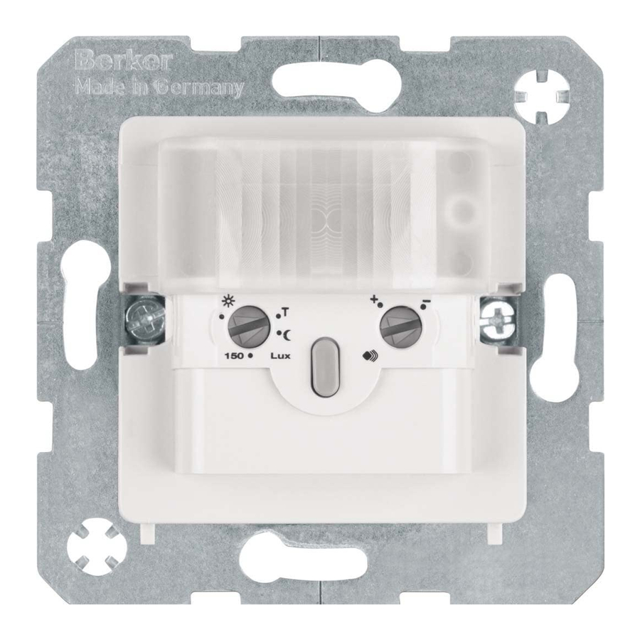
Design and layout of the device

Figure 1: Design and layout of the device
- Motion detector
- Frame (not within scope of delivery)
- Intermediate ring
- Design cover
- Retaining lug
Function
Correct use
- Automatic switching of lighting depending on heat motion and ambient brightness
- Can only be used as individual unit
- Only suitable for use in indoor areas with no drip and no spray water
Product characteristics
- Integrated button for selecting operating mode and switch-off pre-warning
- Operating mode - automatic mode, permanent ON, permanent OFF can be selected
- LED for displaying the operating mode signalling overload and overheating
- Potentiometer for adjusting the response brightness and detection sensitivity
- Delay time: 3 minutes (preset)
- Electronic short circuit protection
- Electronic overload and overheating protection
Automatic mode
The motion detector detects heat motion caused by people, animals, or objects.
- The light will be switched on for the delay time, if movements are detected in the detection area and the set brightness threshold is undershot. Each additional movement in the detection area restarts the delay time.
- Switch-off pre-warning: the connected lighting fl ashes 30 s and 15 s 1 x respectively before the delay time has elapsed. Each movement detected during the switch-off pre-warning restarts the delay time.
- The light will be switched off if no more motion is detected within the detection area and the delay time and switch-off time have elapsed.
Performance after mains breakdown/return of mains supply
- Mains breakdown shorter than 0.2 s: The function is not impaired.
- Mains breakdown longer than 0.2 s: There is no function during the mains breakdown.
- Return of mains supply:
The motion detector executes an initialisation for approx. 30 s, during which the lighting will be switched on. After the initialisation phase has elapsed, the motion detection starts. The load will be switched off if no more motions are detected in the detection area.
Operation

Fig. 2: Operating and display elements
- Status LED behind the cover
- Button
Operation is executed by pushing the button (7) on the motion detector:
- A short press of the button switches the operating modes. The operating mode is displayed via the status LED behind the optics cover of the motion detector.
- Holding down the button activates the switch-off pre-warning. The switch-off pre-warning is displayed via the status LED behind the optics cover of the motion detector (see Table 2).
Selecting the operating mode
- Repeated short press on button until the desired operating mode is selected.
| LED display | Operating mode | Performance |
| - | AUTO | Motion-dependent and brightnessdependent on/off switch of the load |
| red | PERMANENT OFF PERMANENT ON | Load is permanently switched off. Load is permanently switched on. |
Table 1: Display of operating modes
Deactivating switch-off pre-warning
The motion detector is in the factory setting (switch-off pre-warning activated).
- Keep button pressed for approx. 5 s.
LED display flashes 1x. - Quickly press button 1x.
LED display flashes 2x. - To confirm, keep button pressed for approx. 2 s.
The switch-off pre-warning is deactivated.
| LED display | Switch-off pre-warning |
| flashes 1x | activated (factory setting) |
| flashes 2x | deactivated |
Table 2: Selection of the switch-off pre-warning
Information for electricians
Installation and electrical connection

Electrical shock when live parts are touched.
An electric shock can be lethal.
Disconnect the connecting cables before working on the device and cover all live parts in the area!
Selecting installation location
 Observe the motion orientation: a distinction is made between „direct approach" and „transverse motion". Motions transverse to the motion detector can be detected better than motions toward the motion detector (Fig. 3).
- Select an installation location that is free of vibration. Vibrations can cause undesired switching.
- Avoid sources of interference in the detection area. Sources of interference, e.g. heating elements, ventilation systems, air conditioners and lamps that are cooling down can cause undesired switching (Fig. 3).
To avoid disturbing influences, the detection field can be restricted (see Restriction of the detection field).

Fig 3: Installation location of the motion detectors
Connecting and installing the motion detectors
Controller sensor (2-conductor):
L - Outer conductor
 - Outer conductor switched
Motion detector (3-conductor):
L - Outer conductor
 - Outer conductor switched
N - Neutral conductor
The lead is protected by means of a circuit breaker (max 16 A).
- Connect motion detector 1.1 m according to the circuiting diagram (Fig. 4 or 5).
![information]() Observe permissible connected load.
Observe permissible connected load.
![information]() Connect motion detector 1.1 m (2-conductor): only connect dimmable loads.
Connect motion detector 1.1 m (2-conductor): only connect dimmable loads.
![information]() Not suitable for the installation of stair light switches.
Not suitable for the installation of stair light switches. - Insert motion detector (1) into wall box, connecting terminals must be at the bottom.
- Place frame (2) diagonally over both retaining lugs (5) from below.
- Press down the frame and fasten with the intermediate ring (3).
- Snap design cover (4) onto the motion detector.
The motion detector 1.1 m is connected and ready for operation.
")
Fig. 4&5: Motion detector 1.1 m (3-conductor)
Start-up
Overview of adjustment elements

Fig. 6: Operation and adjustment elements
- Response brightness potentiometer
- Sensitivity potentiometer
Setting the detection performance
Test mode must be used to test the detection performance. In test mode, the motion detector works independent of brightness. Each detection switches on the lighting and status LED for 3 seconds. Thereafter motion detection will be deactivated for 2 seconds.
The motion detector is connected and ready for operation.
- Setting the test mode. To do this, set the response brightness potentiometer (Fig. 6, 8) to the T position.
- Leave the detection area and observe the switching behaviour.
- If the motion detector switches on without motion in the detection field, then sources of interference (see Installation location) are present or the sensitivity is set too high.
- Reduce the sensitivity if necessary and blank out or remove any sources of interference by restricting the detection field (see Limiting the detection field).
- Check the detection area using a detection test and adjust if necessary.
If no motions are detected within 3 minutes, the motion detector switches to automatic mode (Factory setting: Response brightness 150 Lux and maximum sensitivity).
Setting the response brightness
The response brightness is the brightness value saved in the motion detector; when this value is undershot the motion detector switches the connected load if movements are detected. The response brightness can be set between approx. 5 ( ) over 150 Lux (factory setting) to daytime operation (
 ). The symbol stands for independent of brightness switching. The response brightness can be variably adjusted in the intermediate areas.he response brightness can be set variably in the intermediate areas.
- To control the lighting in stairwells in accordance with DIN EN12464-1, 2003-3, select the 150 Lux potentiometer setting.
- Turn the response brightness potentiometer (Fig. 6, 8) to the desired position.
Setting the sensitivity
Detection is factory-set to maximum sensitivity. If frequent incorrect detections occur, the sensitivity can be reduced. The sensitivity can be set between approx. 10% (-) to approx. 100% (+).
- Turn the sensitivity potentiometer (Fig. 6, 9) to the desired position.
Limiting the detection field
The detection field is limited with self-adhesive masking film (see accessories) (Fig. 7).
- Unpack masking film and cut out the detection area required
![]() .
.
For orientation, the film is marked at 45°, 90° and 135°. - Stick the masking film carefully onto the optical cover
![]() .
.
In the masked area, heat motions are not registered by the motion detector.
 .
. .
.

Fig. 7: Attaching the masking film for limiting the detection field
Technical data
| Operating voltage | 230 V~ |
| Rated frequency | 50/60 Hz |
Power consumption (Standby)
| < 300 mW < 350 mW |
| Switching capacity of motion detector 2-conductor: | 230 V incandescent lamps and halogen lamps |
| Dimmable conventional transformers | 25... 150 VA |
| Dimmable electronic and dual-mode transformers | 25... 150 VA |
| Compact fluorescent lamps | 12... 48 W |
| Dimmable 230 V LED lamps | 8... 40 W |
| Switching capacity controller sensor 3-conductor: | 230 V incandescent lamps and halogen lamps max. 1000 W |
| Conventional transformers | max. 1000 VA |
| Electronic and dual-mode transformers | max. 1000 W |
| Fluorescent lamps | max. 200 VA |
| Compact fluorescent lamps | max. 350 W |
| 230 V LED lamps | max. 350 W |
| Motors for cos phi 0.6 max | 1 A |
| Interlock time | 2 s |
| Detection area | approx. 10 x 12 m |
| Detection angle | 180 ° |
| Response brightness adjustable | approx. 5... 1000 lx/daytime operation |
| Sensitivity | approx. 10... 1000 % |
| Delay time, preset | 3 min |
| Operating temperature | -5... +45°C |
| Storage temperature | -20... +60°C |
| Relative humidity | 0... 90% (without condensation) |
| Protection class (for complete installation) | II |
| Degree of protection | IP 20 |
| Impact resistance | IK 04 |
| Installation height | 1.1 m |
| Installation depth | 32 mm |
| Screw terminals for max. | 2 x 1.5... 2.5 mm² |
Troubleshooting
After removing a fault, the motion detector is reactivated by pressing button (7). Alternatively, the device can be switched off briefly.
Motion detector does not switch on
- Cause 1: The ambient brightness is greater than the set brightness value.
- Adjust brightness value.
- Cause 2: Motion detector does not detect any motions.
- Increase sensitivity.
Motion detector switches on without any motions
Cause: Sources of interference in the detection area.
- Remove any sources of interference if possible.
- Reduce sensitivity.
- Limit detection area.
Motion detector switches on and off constantly during motion
Cause: Test mode is switched on.
- Adjust the response brightness.
Motion detector switches off despite motion
Cause: The motion detector does not detect any motions.
- Increase sensitivity.
Motion detector does not switch off
Cause: Sources of interference in the detection field, motion detector detects motions constantly.
- Remove any sources of interference if possible.
- Reduce sensitivity.
- Limit detection area.
Status LED flashes repeatedly 3x at a rapid cycle rate
Cause: Overload.
- Reduce connected load.
Status LED flashes repeatedly 4x at a rapid cycle rate
Cause: Overheating.
- Check installation conditions.
- Observe the operating temperature.
Status LED flashes repeatedly 5x at a rapid cycle rate
Cause: Overvoltage.
- Check electrical installation.
Accessories
Design cover: Order no. 1190..
Warranty
We reserve the right to make technical and formal changes to the product in the interest of technical progress.
Our products are under guarantee within the scope of the statutory provisions.
If you have a warranty claim, please contact the point of sale or ship the device postage free with a description of the fault to the appropriate regional representative.

Documents / ResourcesDownload manual
Here you can download full pdf version of manual, it may contain additional safety instructions, warranty information, FCC rules, etc.
Download Berker 2996, 2995 - Motion Detector 1.1 M 2/3-Conductor Manual
Advertisement


Need help?
Do you have a question about the 2996 and is the answer not in the manual?
Questions and answers