Table of Contents
Advertisement
Quick Links
Motion detector 70° surface-mounted
Motion detector 70° surface-mounted
Order-No. : 143 99 09
Motion detector 70° surface-mounted
Order-No. : 143 99 05
Operation- and
Assembly Instructions
1 Safety instructions
Electrical equipment may only be installed and fitted by electrically skilled persons.
Failure to observe the instructions may cause damage to the device and result in fire and
other hazards.
Danger of electric shock. Device is not suitable for disconnection from supply voltage.
Danger of electric shock. Always disconnect before carrying out work on the devise or
load. At the same time, take into account all circuit breakers that supply dangerous
voltage to the device or load.
Do not press on the sensor window. Device can be damaged.
The device is not suitable for use as a burglar alarm or other alarm.
These instructions are an integral part of the product, and must remain with the end
customer.
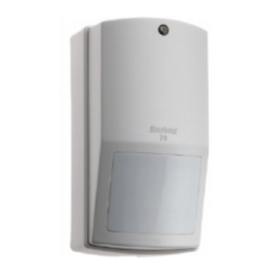
2 Device components
(1) Sensor window
(2) Rear device panel
(3) Central screw
3 Function
Intended use
-
Automatic switching of lighting depending on the heat motion and ambient brightness.
-
Surface-mounting in indoor and outdoor areas
82523521
97-09491-000
Figure 1
Seite 1/8
09.05.2012
Advertisement
Table of Contents

Subscribe to Our Youtube Channel
Related Manuals for Berker 143 99 09


Summary of Contents for Berker 143 99 09
- Page 1 Motion detector 70° surface-mounted Motion detector 70° surface-mounted Order-No. : 143 99 09 Motion detector 70° surface-mounted Order-No. : 143 99 05 Operation- and Assembly Instructions 1 Safety instructions Electrical equipment may only be installed and fitted by electrically skilled persons.
- Page 2 Motion detector 70° surface-mounted Product characteristics Variable installation position Protected against spray water Follow-up time and brightness value settable Test operation for checking the detection area Range can be set in three levels Parallel connection of multiple motion detectors possible Manual switch-on possible with installation button, NC contact Automatic operation The controller detects heat motions of people, animals and objects.
- Page 3 Motion detector 70° surface-mounted 5 Information for electrically skilled persons 5.1 Fitting and electrical connection DANGER! Electrical shock when live parts are touched. Electrical shocks can be fatal. Before carrying out work on the device or load, disengage all the corresponding circuit breakers.
- Page 4 Motion detector 70° surface-mounted i To achieve a rapid response from the motion detector on leaving the building, install the device at a height of less than 2.4 m, centrally above the door. Installing the motion detector Slacken central screw (3) (Figure 1). Remove the housing cover.
- Page 5 Motion detector 70° surface-mounted Figure 5: Setting the follow-up time and the brightness threshold The range of the motion detector can be set in three stages by sliding the internal housing (13) (Figure 6). Figure 6: Setting the range Set the required follow-up time using the adjuster (11). Set the required brightness threshold with the adjuster (12).
- Page 6 Motion detector 70° surface-mounted Connecting the controller Figure 7: Stripping the connection cable The connection cables are equipped with screwless terminals. For secure contacting, connect only single-wire cables with a cross-section of maximum 2.5 mm². Observe the stripping lengths for external cable jacketing and basic insulation (Figure 7). blue, BU N, neutral conductor brown, BN...
- Page 7 Motion detector 70° surface-mounted Figure 9: Connection diagram, switching off motion detectors The motion detector can be switched off using installation switch S1 or S2 (Figure 9). Switching installation switch S1 on again triggers switch-on for the follow-up time. Installation S2 does not do this.
- Page 8 Our products are under guarantee within the scope of the statutory provisions. If you have a warranty claim, please contact the point of sale or ship the device postage free with a description of the fault to the appropriate regional representative. Berker GmbH & Co. KG Klagebach 38 58579 Schalksmühle/Germany...
Need help?
Do you have a question about the 143 99 09 and is the answer not in the manual?
Questions and answers