Advertisement
SMxTAT2SA Quick Start Guide
SMxTAT2SA Quick Start Guide
The SMxTAT2SA(-VT) Smart Managed GbE PoE+ switch (available in
8, 16 or 24 ports) is the next-generation Ethernet switch offering
powerful L2 features with better functionality and usability.
Note: See the SMxTAT2SA Install Guide for important
Cautions
and
Warnings, plus Features, Specifications, Front & Back Panel, LEDs, Mode/Reset button, Installation, Package Contents,
and Troubleshooting, Warranty, Support & Compliance information.
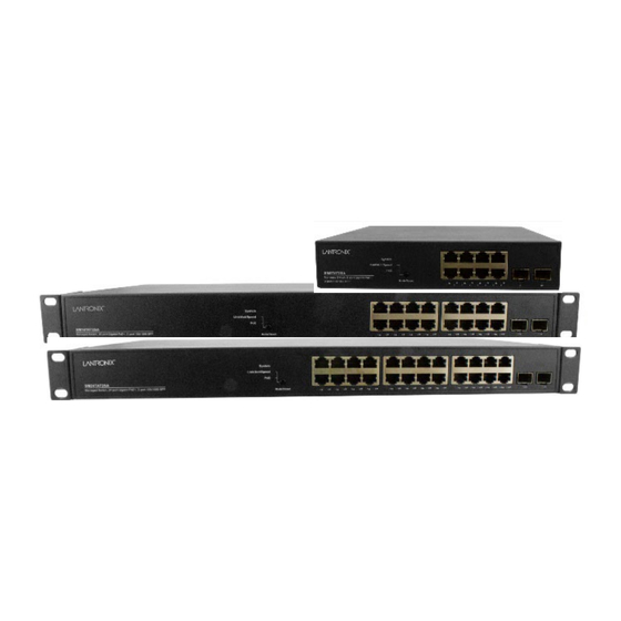
Front and Back Panels
The SM8TAT2SA front and back panels are shown below.
Mode/Reset Button
By pressing the Mode/Reset button for certain period of time, you can:
Change Port Status LED Mode: to read port status correctly in two modes (Link/Act/Speed mode or PoE mode).
Reset the Switch to reboot and get the switch back to the previously saved configuration settings.
Restore the Switch to Factory Defaults: press and hold the Reset button until all port LEDs light. This sets the switch
back to its factory default IP address; log back in to display the First Time Wizard.
LED Descriptions
The LEDs on the front panel provide switch status checking and monitoring. The three types of LEDs are:
System
LED:
Indicates if the switch is powered up correctly, or if there is a
system alarm triggered for troubleshooting.
Mode
LEDs:
Indicates the mode of all ports on the switch. You can press the
Mode/Reset button sequentially to switch between the two different modes
(Link/Activity/Speed mode and PoE mode).
Port Status LEDs: Indicates the current status of each port. You can check these
LEDs to understand the port status in different modes, after changing the mode by pressing the Mode/Reset button.
Switch Installation
Desk, Shelf, or Rack Mount: See the Install Guide. Caution: The switch is an indoor device. If used with outdoor devices,
using a surge protector / suppressor is recommended. 802.3at compliant in Environment A when using an isolated
power supply. For 802.3at Environment B applications, see the Install Guide.
Install SFP Modules: You can install or remove SFP modules without having to power off the switch. 1. Insert the module
into the SFP port. 2. Press firmly so the SFP module seats into the connector. See the Install Guide.
Connect the AC Power Cord: 1. Connect the AC power cord to the switch AC power receptacle. 2. Connect the other end
of the AC power cord to an AC power outlet. 3. If the SYS LED is ON, power connection is correct.
33715 Rev. H
https://www.lantronix.com
Page 1 of 2
Advertisement
Table of Contents

Related Manuals for Lantronix SM TAT2SA Series


Summary of Contents for Lantronix SM TAT2SA Series
- Page 1 Connect the AC Power Cord: 1. Connect the AC power cord to the switch AC power receptacle. 2. Connect the other end of the AC power cord to an AC power outlet. 3. If the SYS LED is ON, power connection is correct. 33715 Rev. H https://www.lantronix.com Page 1 of 2...
- Page 2 Documents: SMxTAT2SA Install Guide 33716, Web User Guide 33717, CLI Reference 33718. Release Notes (version specific). Contact Us: 48 Discovery, Suite 250, Irvine, CA 92618, USA. Toll Free: 800-526-8766. Phone: 949-453-3990. Fax: 949-453-3995. Tech Support: https://www.lantronix.com/technical-support/. Sales Offices: www.lantronix.com/about/contact. 33715 Rev. H https://www.lantronix.com...
Need help?
Do you have a question about the SM TAT2SA Series and is the answer not in the manual?
Questions and answers