
Related Manuals for Lantronix SM8TAT2SA


Summary of Contents for Lantronix SM8TAT2SA
- Page 1 SM8TAT2SA, SM16TAT2SA, SM24TAT2SA Smart Managed Switches, 8-/16-/24-Port Gigabit PoE+, 2-Port 100/1000 SFP Slots Install Guide Part Number 33716 Revision L June 2022...
- Page 2 SMxTAT2SA Install Guide Intellectual Property © 2022 Lantronix, Inc. All rights reserved. No part of the contents of this publication may be transmitted or reproduced in any form or by any means without the written permission of Lantronix. Lantronix is a registered trademark of Lantronix, Inc. in the United States and other countries. All other trademarks and trade names are the property of their respective holders.
- Page 3 Lantronix SMxTAT2SA Install Guide Cautions and Warnings Cautions indicate that there is the possibility of poor equipment performance or potential damage to the equipment. Warnings indicate that there is the possibility of injury to person. Cautions and Warnings appear here and may appear throughout this manual where appropriate. Failure to read and understand the information identified by this symbol could result in poor equipment performance, damage to the equipment, or injury to persons.
-
Page 4: Table Of Contents
Lantronix SMxTAT2SA Install Guide Contents Chapter 1 Introduction ............................5 ................................5 Key Features ...................................5 Benefits ...............................6 Ordering Information ................................6 Specifications ..............................8 Software Features ............................... 10 About This Manual ..............................10 Related Manuals Chapter 2 Introduction and Product Description ....................11 ................................ -
Page 5: Chapter 1 Introduction
The SMxTAT2SA delivers 8/16/24 (10M/100M/1G) RJ45 ports with 8 PoE+ ports (supports 802.3 at/af and total up to 130W on the SM8TAT2SA) and 2 GbE SFP ports. The SMxTAT2SA provides high hardware performance and environment flexibility for SMBs and Enterprises. -
Page 6: Ordering Information
Specifications Port Configuration Total Ports RJ45 (10M/100M/1G) Uplinks (100M/1G) Telnet SM8TAT2SA = 10 2 SFP Via any RJ45 port SM16TAT2SA = 18 2 SFP Via any RJ45 port SM24TAT2SA = 26 2 SFP... - Page 7 Dimensions, Weights, Mounting Dimensions (WxHxD) Weight Mounting Type Model Millimeters Inches Kilograms Pounds SM8TAT2SA 220 x 44 x 242 8.6 x 1.7 x 9.5 Desktop, Wall, Rack SM16TAT2SA 442x 44x 211 17.4x 1.7x 8.3 Desktop, Wall, Rack SM24TAT2SA 442x 44x 211 17.4x 1.7x 8.3...
-
Page 8: Software Features
Lantronix SMxTAT2SA Install Guide Certifications Electromagnetic Emissions (EMC) and Safety EMC: CE, FCC Part 15 Class A Safety: IEC62368-1/EN62368-1, UL Listed EN 55032:2012, EN 55024:2010 Directive 2014/30/EU, Directive 2015/863/EU Low-Voltage Directive 2014/35/EU 2011/65/EU EN 50581:2012 Normas Oficiales Mexicans (NOM) Software Features Layer 2 Switching •... - Page 9 Lantronix SMxTAT2SA Install Guide IP Source Guard Prevents illegal IP address from accessing to specific port in the switch RADIUS Supports RADIUS authentication switch as a client TACACS+ Up to 5 TACACS+ servers are supported Prevents traffic on a LAN from being disrupted by a broadcast, multicast, or unicast...
-
Page 10: About This Manual
For Lantronix Drivers, Firmware, Manuals, Product Notifications, Warranty Policy & Procedures, etc. go to the Lantronix Technical Resource Center. Note that this manual provides links to third party web sites for which Lantronix is not responsible. 33716 Rev. L https://www.lantronix.com/... -
Page 11: Chapter 2 Introduction And Product Description
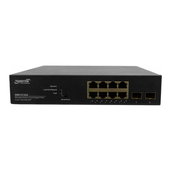
Mode/Reset button operation and functions. Front and Back Panels The front panels are similar except for port counts. The back panels are similar except for overall width. Figure 1: SM8TAT2SA Front and Back Panels Figure 2: SM16TAT2SA Front and Back Panels 33716 Rev. L... - Page 12 Lantronix SMxTAT2SA Install Guide Figure 3: SM24TAT2SA Front and Back Panels 33716 Rev. L https://www.lantronix.com/...
-
Page 13: Led Descriptions
Lantronix SMxTAT2SA Install Guide LED Descriptions The LEDs on the front panel provide switch status checking and monitoring. There are three types of LEDs as follows: System LED Indicates if the switch is powered up correctly, indicates if there is a system alarm triggered for troubleshooting. - Page 14 Lantronix SMxTAT2SA Install Guide By pressing the Mode/Reset button for less than 2 seconds to change LED modes (Link/Act/Speed Mode or PoE Mode) you can check the port status by reading the LED behaviors per the table below. Table 3: Port Status LEDs...
-
Page 15: Mode/Reset Button
Lantronix SMxTAT2SA Install Guide When PoE Mode LED Lit Color State Description Green The port is enabled and supplying power to connected device. An abnormal state, such as overload status, has been detected in the Amber switch. RJ45 Ports The port has no active network cable connected, or it is not connected a PoE PD device. -
Page 16: Chapter 3 Installation
Lantronix SMxTAT2SA Install Guide Chapter 3 Installation Package Contents Carefully unpack the package contents. Make sure no items are missing or damaged. Please save the packaging for possible future use. The Switch • AC Power cord (country specific) • Four adhesive rubber feet •... -
Page 17: Mounting The Switch On Desk Or Shelf
Lantronix SMxTAT2SA Install Guide Mounting the Switch on Desk or Shelf Step 1: Verify that the workbench is sturdy and reliably grounded. Step 2: Attach the four adhesive rubber feet to the bottom of the switch. Figure 6: Attaching the Rubber Feet Mounting the Switch in a 19-inch Rack Step 1: Attach the mounting brackets to both sides of the chassis. -
Page 18: Installing Sfp Modules
You can install or remove a mini-GBIC SFP module from a SFP port without having to power off the switch. Note: with Port Mode set to Auto, these Copper SFPs can be used: TN-SFP-T-MG, TN-GLC-T-MG, and TN-GLC-T. Note: see the related SFP device manual for important Safety warnings. See the Lantronix SFP page for our full line of SFP transceivers. -
Page 19: Connecting The Ac Power Cord
The switch ships with a country specific AC Power cord. To order the corresponding country specific power cord, add the Country Code extension to the end of the SKU (e.g., SM8TAT2SA-NA = North America, -LA = Latin America, -EU = Europe, -UK = United Kingdom, -SA = South Africa, -JP = Japan, -OZ = Australia, -BR = Brazil). -
Page 20: Chapter 4 Initial Switch Configuration
Lantronix SMxTAT2SA Install Guide Chapter 4 Initial Switch Configuration Initial Switch Configuration via Web Browser When you power up the switch the first time, a First Time Wizard is presented. On subsequent power ups, you can perform the initial switch configuration using a web browser. See the Quick Start Guide for First Time Wizard information. -
Page 21: Initial Switch Configuration Via Cli
Lantronix SMxTAT2SA Install Guide Figure 11: Web Interface Login page If you do not see the above login page, perform these steps: - Refresh the web page. - Check to see if there is an IP conflict issue. - Clean browser cookies and temporary internet files. -
Page 22: Chapter 5 Troubleshooting, Support, And Compliance
Lantronix SMxTAT2SA Install Guide Chapter 5 Troubleshooting, Support, and Compliance Troubleshooting The following table provides steps to troubleshoot problems by taking actions based on the suggested solutions. Table 5: Troubleshooting Procedure Symptom Possible Cause Suggested Solution 1. Check if correct power cord is connected firmly to the switch and to the AC outlet socket. -
Page 23: Poe Modes And Compliance
802.3af/at "compatible" PDs typically can provide power using only Mode B. Typical PD Power Requirements □ 1.8 Watts: Lantronix’ M/GE-ISW-SFP-01-PD (Class 1 Powered Device (0.44 - 3.84 Watts). □ 13W: IP Camera, VoIP Phone, Wireless Access Point, Networked Audio. □... -
Page 24: Troubleshooting Poe Problems
2. PoE cables are intended for intrabuilding use only. Connecting your Lantronix switch directly to PoE cables that run outside the building in which the switch is housed will void the user's warranty and could create a fire or shock hazard. - Page 25 Lantronix SMxTAT2SA Install Guide 12. Pre-standard and post-standard VoIP phones may use different detection and connect / disconnect methods. Note that PD detection occurs when an Ethernet device is first connected to a PoE port. If a non-PoE device is connected to a PoE port, detection is deactivated. If the non-PoE device is later disconnected and replaced by a PD, the switch may not detect it immediately.
-
Page 26: Recording Device And System Information
A description of any action(s) already taken to resolve the problem (e.g., changing mode, rebooting, etc.): ____________________________________________________________________________________________________________________ ____________________________________________________________________________________________________________________ ____________________________________________________________________________________________________________________ The serial and revision numbers of all involved Lantronix products in the network: _____________________________________________________________________________________________________________________ A description of your network environment (layout, cable type, etc.): ______________________________________________ _______________________________________________________________________________________________________________________ _______________________________________________________________________________________________________________________ The device history (i.e., have you returned the device before, is this a recurring problem, etc.): ____________________... -
Page 27: Compliance Information
Declaration of Conformity Manufacture’s Name: Lantronix, Inc. Manufacture’s Address: 7535 Irvine Center Drive, Suite 100, Irvine, California 92618 Declares that the product(s): SM8TAT2SA, SM16TAT2SA, SM24TAT2SA Conform(s) to the following Product Regulations: FCC Part 15 Class A, EN 55032:2012, EN 55024:2010... - Page 28 Lantronix SMxTAT2SA Install Guide SMxTAT2SA EU Compliance The equipment is in accordance with the procedures as given in European Council Directive 2014/30/EU. The equipment Passed the test performed according to European Standard EN 55032:2012/AC:2013 Class A, EN61000-3-2:2014, EN 61000-3-3:2013 and EN 55024:2010 (IEC 61000-4-2 Edition 2.0 2008-12, IEC 61000-4-3 Edition 3.2 2010-04, IEC 61000-4-4 Edition 3.0 2012-04,...
- Page 29 Lantronix SMxTAT2SA Install Guide Electrical Safety Warnings Electrical Safety IMPORTANT: This equipment must be installed in accordance with safety precautions. Elektrische Sicherheit WICHTIG: Für die Installation dieses Gerätes ist die Einhaltung von Sicherheitsvorkehrungen erforderlich. Elektrisk sikkerhed VIGTIGT: Dette udstyr skal installeres i overensstemmelse med sikkerhedsadvarslerne.
- Page 30 Irvine, CA 92618, USA Toll Free: 800-526-8766 Phone: 949-453-3990 Fax: 949-453-3995 Technical Support +1.952.358.3601, 1.800.260.1312, or https://www.lantronix.com/technical-support/ Sales Offices For a current list of our domestic and international sales offices, go to the Lantronix web site at www.lantronix.com/about/contact. 33716 Rev. L https://www.lantronix.com/...
Need help?
Do you have a question about the SM8TAT2SA and is the answer not in the manual?
Questions and answers