
Related Manuals for EL-CELL PAT-Cell-Opto-10


Summary of Contents for EL-CELL PAT-Cell-Opto-10
- Page 1 User Manual Release 1.3 PAT-Cell-Opto-10 Electrochemical test cell © 2023 EL-Cell GmbH...
- Page 2 PAT-Cell-Opto-10 Disclaimer EL-Cell GmbH makes no assurances or warranties with respect to this manual and, to the extent permitted by law, limits its liability for violation of any implied warranty to the substitution of this manual for another. In addition, EL -Cell GmbH reserves the right to revise this publication at any time without notice to anyone.
- Page 3 User Manual PAT-Cell-Opto-10 Manufacturer and customer service EL-Cell GmbH Tempowerkring 8 21079 Hamburg – Germany Telephone: +49 40 79012-734 Telefax: +49 40 79012-736 Email: info@el-cell.com Website: el-cell.com Technical support Telephone: +49 40 79012-734 Email: support@el-cell.com Website: el-cell.com/support/technical-support/ Please always quote the serial number on the nameplate when making customer service inquiries.
-
Page 4: Table Of Contents
Storage instructions ........................5 Obtaining documents and information ..................6 Product Description ...................... 7 Features ............................7 Working principle of the PAT-Cell-Opto-10 (side-by-side setup of electrodes): ... 8 Technical data ....................... 9 Intended use ........................9 Safety Precautions ......................9 Assembly ........................ -
Page 5: Preamble
User Manual PAT-Cell-Opto-10 1 Preamble 1.1 Purpose and target audience This manual covers the structure, function, operation and maintenance of the device described. It is intended for the end users of the device. An end user can be described as any person who interacts directly with the device. -
Page 6: Obtaining Documents And Information
User Manual PAT-Cell-Opto-10 1.3 Obtaining documents and information A current version of the documentation is available on the following website : https://el-cell.com/support/manuals/ Alternatively, you can scan this QR code, to access the website: Page 6 of 23 Release 1.3... -
Page 7: Product Description
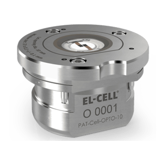
User Manual PAT-Cell-Opto-10 2 Product Description The PATCell-Opto-10 test cell is designed for operando characterization of electrodes using optical methods such as light microscopy or Raman spectroscopy in reflection mode. The test cell utilizes the cableless PAT socket for cell connection. This way, it can be directly plugged into a PAT battery tester like the PAT-Tester-x-8 or a PAT docking station to connect it to a third-party battery tester. -
Page 8: Working Principle Of The Pat-Cell-Opto-10 (Side-By-Side Setup Of Electrodes)
User Manual PAT-Cell-Opto-10 2.2 Working principle of the PAT-Cell-Opto-10 (side-by-side setup of electrodes): Inspection area (up to 18 mm) Sapphire glass window Electrode 2 Electrode 1 Lid sealing foil (PE) Sample holder Plunger/ Electrode R Glass fiber separator Inner sleeve II... -
Page 9: Technical Data
Dead volume: 1.8 cm³ ▪ 4 Intended use The PAT-Cell-Opto-10 test cell is an electrochemical measuring instrument designed for use in a laboratory environment. It may only be used by trained personnel and only as described in this manual. 5 Safety Precautions Use proper safety precautions when using hazardous electrode materials and electrolytes. -
Page 10: Assembly
6.2. Instructions for assembling the cell for the side-by-side arrangement of electrodes. 6.3. Instructions for assembling the cell for the face-to-face arrangement of electrodes. These instructions can also be viewed as videos on our website el-cell.com. Page 10 of 23 Release 1.3... -
Page 11: Lid Assembly
User Manual PAT-Cell-Opto-10 6.1 Lid assembly: 1. Turn the lid upside down. Insert the foil sealing into the lid. 2. Insert the window. 3. Insert the window thrust ring. 4. Attach the window flange and screw in the screws using the torque screwdriver 0.2 Nm. -
Page 12: Assembling The Cell With A Side-By-Side Sample Holder
User Manual PAT-Cell-Opto-10 6.2 Assembling the cell with a side-by-side sample holder: 1. Assemble the lid as described above. Then insert the lower piston into the inner sleeve. 2. Use the loading tweezers to push the piston into the sleeve. - Page 13 User Manual PAT-Cell-Opto-10 5. Attach the electrode strips to the sample holder. 6. Attach the sample holder to the piston assembly. 7. Insert the assembly into the cell base. 8. Drop the electrolyte onto the separator/electrodes. Use only the amount of electrolyte necessary to impregnate the porous material.
- Page 14 11. Double-check the proper alignment of the electrode strips. Then press down the lid and tighten the three screws firmly with the 2.5 mm hexagon screwdriver. 12. The PAT-Cell-Opto-10 is now ready for testing. Page 14 of 23 Release 1.3...
-
Page 15: Assembling The Cell With A Face-To-Face Sample Holder
User Manual PAT-Cell-Opto-10 6.3 Assembling the cell with a face-to-face sample holder: 1. Follow the lid assembly steps. Then insert the lower piston into the inner sleeve. 2. Use the loading tweezers to push the piston into the sleeve. 3. Place the assembly into the cell base. - Page 16 User Manual PAT-Cell-Opto-10 5. Put the separator on top. The separator must not be more than 10 mm in diameter. A smaller separator may be useful to prevent the sample holder from coming into contact with the electrolyte. 6. Use the loading tweezer again to push the cell stack further down.
- Page 17 User Manual PAT-Cell-Opto-10 9. Push down the electrode stack using the loading tweezer. 10. Insert the contact ring. 11. Put the holed current collector on top. Choose the hole size depending on the magnification used by the microscope. 12. Insert the second foil seal.
- Page 18 14. Finally, screw the cover on with the 2.5 mm hexagon screwdriver. 15. The PAT-Cell-Opto-10 is now ready for testing. Page 18 of 23 Release 1.3...
-
Page 19: Connecting The Test Cell
User Manual PAT-Cell-Opto-10 7 Connecting the test cell The PAT-Cell-Opto-10 is connected via the cableless PAT socket. It can be directly plugged into any EL-Cell PAT-Tester or PAT docking station. 8 Disassembly and Cleaning When working with aprotic, moisture-sensitive electrolytes such as LiPF , it is best to always leave the cell base and cell lid in the glove box. -
Page 20: Unpacking
Contact the factory if anything is missing or damaged. NOTE: Damaged shipments must remain with the original packaging for freight company inspection. List of Components: PAT-Cell-Opto-10 test cell with flat socket, fully equipped for use in both 2-electrode and 3-electrode (reference) configuration Windows seal (10 pcs.) ECC1-05-0016-B/X Separator 10.0 mm x 0.26 mm, GF/A (10 pcs.) -
Page 21: Components
User Manual PAT-Cell-Opto-10 10 Components 10.1 PAT-Cell-Opto-10 Page 21 of 23 Release 1.3... -
Page 22: Lid Unit (Opto-10) 18 Mm
User Manual PAT-Cell-Opto-10 10.2 Lid unit (OPTO-10) 18 mm Page 22 of 23 Release 1.3... -
Page 23: Warranty
User Manual PAT-Cell-Opto-10 11 Warranty For a period of one year from the date of shipment, EL -Cell GmbH (hereinafter Seller) warrants the goods to be free from defects in material and workmanship to the original purchaser. During the warranty period, Seller agrees to repair or replace defective and/or nonconforming goods or parts without charge for material or labor, or, at the Seller’s option, demand return...
Need help?
Do you have a question about the PAT-Cell-Opto-10 and is the answer not in the manual?
Questions and answers