Table of Contents
Advertisement
Quick Links
Advertisement
Table of Contents

Related Manuals for EL-CELL PAT-Terminal-1


Summary of Contents for EL-CELL PAT-Terminal-1
- Page 1 © 2016 EL-CELL GmbH User Manual Release 1.0 PAT-Terminal-1 © 2023 EL-Cell GmbH...
- Page 2 PAT-Terminal-1 Manual Disclaimer EL-Cell GmbH makes no assurances or warranties with respect to this manual and, to the extent permitted by law, limits its liability for violation of any implied warranty to the substitution of this manual for another. In addition, EL-Cell GmbH reserves the right to revise this publication at any time without notice to anyone.
- Page 3 PAT-Terminal-1 Manual Manufacturer and customer service EL-Cell GmbH Tempowerkring 8 21079 Hamburg – Germany Telephone: +49 40 79012-734 Telefax: +49 40 79012-736 Email: info@el-cell.com Website: el-cell.com Technical support Telephone: +49 40 79012-734 Email: support@el-cell.com Website: el-cell.com/support/technical-support/ Please always quote the serial number on the nameplate when making customer service inquiries.
-
Page 4: Table Of Contents
PAT-Terminal-1 Manual Table of contents Preamble ..............................6 Purpose and target audience ....................6 Storage instructions ........................6 Obtaining documents and information................... 7 For your safety ............................8 Explanation of the safety instructions ..................8 2.1.1 Terms used ..........................8 2.1.2... - Page 5 PAT-Terminal-1 Manual Start-up ..............................20 Operation as a stand-alone device ..................20 4.1.1 Operation outside the glove box ..................20 4.1.2 Operation inside the glove box ..................20 4.1.3 Performing an impedance test ................... 21 Operation as test channel in a PAT-Tester-x setup ............21 Switching on and off.........................
-
Page 6: Preamble
Terminal-1. It is intended for the end users of the device. An end user can be described as any person who interacts directly with the PAT-Terminal-1. The term "end user" usually includes laboratory personnel who have been specifically trained to operate this instrument and are familiar with all the precautions required to work in th e laboratory. -
Page 7: Obtaining Documents And Information
PAT-Terminal-1 Manual 1.3 Obtaining documents and information A current version of the documentation is available on the following website : https://el-cell.com/support/manuals/ Alternatively, you can scan this QR code, to access the website: Page 7 of 28 Release 1.0... -
Page 8: For Your Safety
PAT-Terminal-1 Manual 2 For your safety 2.1 Explanation of the safety instructions In this manual, certain recurring terms and symbols are used to warn you of hazards or to give you instructions that are important to prevent injury and damage. It is essential that you read and follow these notes in order to avoid accidents and damage. -
Page 9: Product Safety And Hazards
PAT-Terminal-1 Manual 2.2 Product safety and hazards The device described is technically mature, is manufactured using high -quality materials and is tested at the factory before delivery. It complies with the state of the art and the recognized safety regulations. -
Page 10: Intended Use
PAT-Tester-x. Other uses can lead to hazards and damage. NOTICE The PAT-Terminal-1 may only be used with test cells of the PAT series. Other cell types must be connected using the appropriate adapters available from the manufacturer . 2.5 Modifications and conversions The PAT-Terminal-1 must not be modified or altered without authorization. -
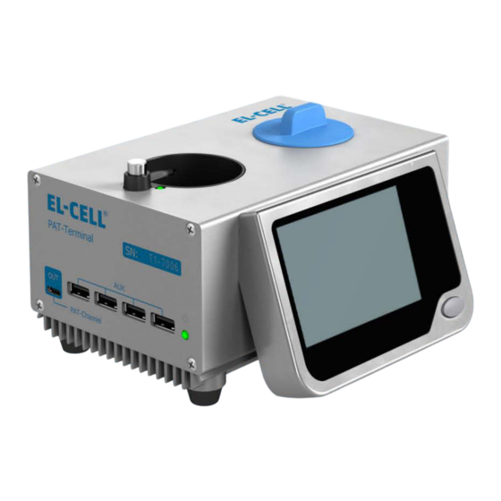
Page 11: Description And Design
It has an LC display for displaying various parameters of the test cell used. The PAT-Terminal-1 can be operated as a stand-alone unit in a glove box to perform functional tests on test cells and to facilitate cell sensor adjustment. Once connected to a PAT Controller-8, it can be used as a normal test channel for full electrochemical measurements. -
Page 12: Connections
PAT-Terminal-1 Manual 3.2.1 Connections Front side PAT-Channel connector (USB 2 Type C): For connecting another PAT-Channel-1 AUX ports (USB 2.0): For future applications Back side PAT-Controller connector (USB 2 Type C): Used to supply power via the supplied USB power adapter or to connect to a PAT-Controller. -
Page 13: Pin Assignment D-Sub Connector
PAT-Terminal-1 Manual Top side D-Sub connector: This connector is used to connect a battery test cell or docking station via D-Sub cable. USB 2.0 port: Used for power supply and data transfer of external devices. PAT socket: This socket is used to connect a PAT series battery test cell or PAT -Adapter. -
Page 14: Technical Data
PAT-Terminal-1 Manual 3.3 Technical data 164 mm 97 mm 141 mm 3.3.1 Dimensions Weight 1.3 kg (without insertd test cell) Height 97 mm Length 164 mm Width 141 mm 3.3.2 General device specifications Device name PAT-Terminal-1 Type Potentiostat/Galvanostat/Impedance analyzer Operating temperature range -20 to +40 °C... -
Page 15: Test Channel Performance Data
PAT-Terminal-1 Manual 3.3.3 Test channel performance data -7 to +7 V Voltage range ±100 mA Current 3 electrodes plus sense wires, Connection matrix Cell and electrode connections 2x24 Bit 1x18 Bit 500 kHz (fast) Bandwidth ranges (Stability Factor) 50 kHz (medium) -
Page 16: Applied Guidelines And Standards
PAT-Terminal-1 Manual 3.4 Applied guidelines and standards The product described is in conformity with the following harmonized standards: EN 61010-1:2010 Sicherheitsbestimmungen für elektrische Mess-, Steuer-, Regel- und Laborgeräte – Teil 1: Allgemeine Anforderungen (DIN EN 61010-1, VDE 0411-1:2011-07) Safety requirements for electrical equipment for... - Page 17 PAT-Terminal-1 Manual (IEC 61326-2-3:2012) EN 61326-2-3:2013-07 Elektrische Mess-, Steuer-, Regel- und Laborgeräte - EMV- Anforderungen - Teil 2-3: Besondere Anforderungen - Prüfanordnung, Betriebsbedingungen und Leistungsmerkmale für Messgrößenumformer mit integrierter oder abgesetzter Signalaufbereitung (DIN EN 61326-2-3:2013-07, VDE 0843-20-2-3:2013-07) Electrical equipment for measurement, control and laboratory...
- Page 18 PAT-Terminal-1 Manual Page 18 of 28 Release 1.0...
-
Page 19: Checking For Completeness And Transport Damage
PAT-Terminal-1 Manual 3.5 Checking for completeness and transport damage Check the completeness of the scope of delivery against the delivery note. • Check the device for damage. • If you find deviations from the scope of delivery or damage, please notify the carrier and the manufacturer. -
Page 20: Start-Up
NOTICE If the PAT-Terminal-1 is not supplied with power even though the cables are connected, disconnect the USB cable in the glove box from the feedthrough, turn it 180 degrees and plug it back in. -
Page 21: Performing An Impedance Test
PAT socket. 4.3 Switching on and off The PAT-Terminal-1 switches on as soon as it is connected to the power supply. To switch off, it is sufficient to disconnect the device from the power supply. Page 21 of 28... -
Page 22: Inserting And Removing Test Cells
PAT-Terminal-1 Manual 4.4 Inserting and removing test cells 4.4.1 Inserting a PAT series test cell Insert the cell into the PAT socket until the cell audibly click s into place. This ensures that the electrical contact is properly established. 4.4.2 Removing a PAT series test cell To remove a cell, press the eject button next to the PAT socket to release the lock (1) and then remove the cell (2). -
Page 23: Lc-Display
PAT-Terminal-1 Manual 5 LC-Display Display item Meaning Cell ID (in this case F0001) Cell ID of the test cell used Force The force acting on the cell stack in Newtons (if sensor is present). Press The gas pressure in the test cell in mbar (if... -
Page 24: Malfunctions, Warning And Error Messages
PAT-Terminal-1 Manual 6 Malfunctions, warning and error messages WARNING After removing covers, electrically live parts may be exposed. You may suffer an electric shock if you touch these parts. Disconnect the power plug before removing any covers. Only qualified electricians may work on the electrical equipment of the devices. -
Page 25: Led Pat Socket
PAT-Terminal-1 Manual 6.1.2 LED PAT socket Signal Bedeutung Red, flashes every three seconds Channelboard is initialized Red, permanent Channelboard error Green, permanent Channelboard works normally Page 25 of 28 Release 1.0... -
Page 26: Maintenance And Repair
If rust spots occur due to contamination, the affected areas must be cleaned and polished immediately. Protect the PAT-Terminal-1 from dust and splash water. Page 26 of 28 Release 1.0... -
Page 27: Storage And Disposal
PAT-Terminal-1 Manual 8 Storage and disposal 8.1 Storage The device may only be stored under the following conditions: dry and in a closed, dust-free room • frost-free • disconnected from the power supply • 8.2 Disposal The device must not be disposed of in normal household waste. Observe the applicable legal regulations. -
Page 28: Warranty
PAT-Terminal-1 Manual 9 Warranty For a period of one year from the date of shipment, EL-Cell GmbH (hereinafter Seller) warrants the goods to be free from defect in material and workmanship to the original purchaser. During the warranty period, Seller agrees to repair or replace defective and/or nonconforming goods or parts without charge for material or labor, or, at the Seller’s option, demand return...
Need help?
Do you have a question about the PAT-Terminal-1 and is the answer not in the manual?
Questions and answers