
Related Manuals for EL-CELL PAT-Tester-x-8


Summary of Contents for EL-CELL PAT-Tester-x-8
- Page 1 User Manual Release 1.1 PAT-Tester-x-8 Modular battery test system with up to 8 test channels © 2023 EL-Cell GmbH...
- Page 2 The information in this manual has been carefully checked and believed to be accurate; however, no responsibility is assumed for inaccuracies. EL-Cell GmbH maintains the right to make changes without further notice to products described in this manual to improve reliability, function, or design. EL -Cell GmbH does not assume any liability arising from the use or application of this product.
- Page 3 User Manual PAT-Tester-x-8 Content 1 Product description ........................... 4 Included component manuals PAT-Controller-8 …………………………………………………………………………………………………………………………….. PAT-Channel-1 …..……………….……………………………………………………………………………………………………….. PAT-Terminal-1 …………………………………………………………………………………………………………………………… …. Page 3 of 6 Release 1.1...
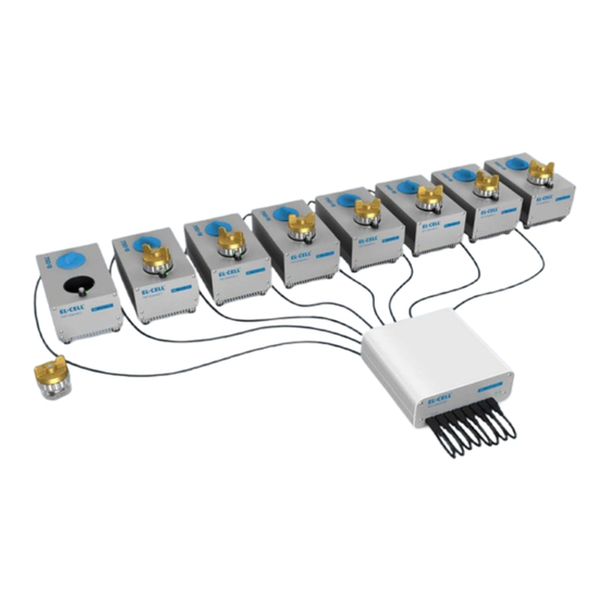
- Page 4 PAT-Tester-x-8 1 Product description The PAT-Tester-x-8 is suited for small scale and special purpose testing. It is a modular battery tester designed for small test series and special measuring cells. The PAT-Tester-x consists of two main components, the PAT-Controller-8 and up to 8 test channels.
- Page 5 User Manual PAT-Tester-x-8 1.1 Hardware setup example EL-Software Client PAT-Channel-1 with battery test cell EL-Software Server PAT-Controller-8 1.2 Testing setup examples PAT-Tester-x-8 setup with connected PAT-Channel-1 and PAT-Terminal-1 running PAT- Cells Page 5 of 6 Release 1.1...
- Page 6 User Manual PAT-Tester-x-8 PAT-Tester-x-8 setup with a connected external PAT-Heater-4 docking station running PAT-Cell-HT test cells. PAT-Tester-x-8 setup for running an ECD-4-nano dilatometer inside a temperature chamber Page 6 of 6 Release 1.1...
- Page 7 User Manual Release 1.2 PAT-Controller-8 Control box for up to 8 test channels © 2023 EL-CELL GmbH...
- Page 8 The information in this manual has been carefully checked and believed to be accurate; however, no responsibility is assumed for inaccuracies. EL-Cell GmbH maintains the right to make changes without further notice to products described in this manual to improve reliability, function, or design. EL -Cell GmbH does not assume any liability arising from the use or application of this product.
-
Page 9: Table Of Contents
User Manual PAT-Controller-8 Content 1 Product description ........................... 4 2 Features ................................ 5 3 Technical data ............................. 5 4 Connections and display .......................... 6 5 Safety precautions ............................. 7 6 Installation ..............................8 7 Cleaning ............................... 9 8 Unpacking ..............................9 9 EC declaration of conformity ........................ -
Page 10: Product Description
User Manual PAT-Controller-8 1 Product description The PAT-Controller-8 is a core component of each PAT-Tester-x. It is used to manage the connected test channels and enables data traffic to the EL -Software server. The PAT-Controller features a network port for server communication and USB ports for connection to up to 8 PAT-Channel-1 or PAT-Terminal-1 devices. -
Page 11: Features
User Manual PAT-Controller-8 2 Features LAN Port (RJ45) for server connectivity ▪ 8 USB 2.0 Hi-Speed, type C ports for connecting PAT-Channel-1 or PAT-Terminal-1 ▪ 3 Technical data Height: 78 mm ▪ Length: 168 mm ▪ Width: 170 mm ▪ Weight: 1.7 kg ▪... -
Page 12: Connections And Display
User Manual PAT-Controller-8 4 Connections and display Front: USB 2.0 Hi-Speed, type C ports for PAT-Channel-1 connection HDD-LED (yellow): Indicates hard drive (SSD) access. Power-LED (green): Indicates deivce is powered on. Power-LED (red): ): Indicates a fan fault or over-temperature fault. After powering up the PAT-Controller, the red LED lights up for 1 second. - Page 13 Risk of fire or electric shock when using a mains plug adapter that is not specified. Use only the EL-Cell provided power supply approved for use with this device. Page 7 of 13...
- Page 14 User Manual PAT-Controller-8 6 Installation Note: To operate the PAT-Controller-8 you need access to an Ethernet Local Area Network (LAN). EL-Software Server (the server application of EL software) must be installed on the LAN server and EL-Software Client (the client component of EL software) on at least one client PC. The installation instructions for EL-Software can be found in the corresponding manual.
- Page 15 Check the contents of the packages against the list given below to verify that you have received all of the required components. Contact EL-CELL, if anything is missing or damaged. NOTE: Damaged shipments must remain within the original packaging for freig ht company inspection.
- Page 16 User Manual PAT-Controller-8 9 EC declaration of conformity Page 10 of 13 Release 1.2...
- Page 17 User Manual PAT-Controller-8 The products described are in conformity with the following harmonized standards: EN 61010-1:2010 Sicherheitsbestimmungen für elektrische Mess-, Steuer-, Regel- und Laborgeräte – Teil 1: Allgemeine Anforderungen (DIN EN 61010-1, VDE 0411-1:2011-07) Safety requirements for electrical equipment for measurement, control and laboratory use - Part 1: General requirements (IEC 61010-1:2010 + Cor.
- Page 18 User Manual PAT-Controller-8 EN 61326-2-3:2013-07 Elektrische Mess-, Steuer-, Regel- und Laborgeräte - EMV- Anforderungen - Teil 2-3: Besondere Anforderungen - Prüfanordnung, Betriebsbedingungen und Leistungsmerkmale für Messgrößenumformer mit integrierter oder abgesetzter Signalaufbereitung (DIN EN 61326-2-3:2013-07, VDE 0843-20-2-3:2013-07) Electrical equipment for measurement, control and laboratory use - EMC requirements - Part 2-3: Particular requirements - Test configuration, operational conditions and performance criteria for transducers with integrated or remote signal...
- Page 19 User Manual PAT-Controller-8 10 Technical support Technical support for this product is exclusively provided by EL-Cell GmbH. EL-Cell GmbH Tempowerkring 8 21079 Hamburg - Germany phone: +49 40 79012-734 fax: +49 40 79012-736 e-mail: support@el-cell.com web: el-cell.com 11 Warranty For a period of one year from the date of shipment, EL -Cell GmbH (hereinafter Seller) warrants the goods to be free from defect in material and workmanship to the original purchaser.
- Page 20 User Manual Release 1.03 PAT-Channel-1 Single channel station for one test cell © 2023 EL-CELL GmbH...
- Page 21 The information in this manual has been carefully checked and believed to be accurate; however, no responsibility is assumed for inaccuracies. EL-Cell GmbH maintains the right to make changes without further notice to products described in this manual to improve reliability, function, or design. EL -Cell GmbH does not assume any liability arising from the use or application of this product.
- Page 22 User Manual PAT-Channel-1 Content Product description ........................... 4 Features ..............................5 Technical data ............................. 5 Specifications ............................6 Accuracy Contour Plot ........................6 General ............................. 6 Voltage ............................. 7 Current ............................. 7 Impedance (each channel) ......................8 Other ..............................8 Construction and Connections .......................
-
Page 23: Product Description
User Manual PAT-Channel-1 1 Product description The PAT-Channel-1 is a fully featured, single channel potentiostat / galvanostat/ impedance analyzer which is operated in conjunction with a PAT-Controller. It has a docking socket for one PAT series test cell and external connectors to connect a test cell of a different type or a separate docking station. -
Page 24: Features
User Manual PAT-Channel-1 2 Features Fully equipped with PStat/GStat/EIS ▪ Voltage: +/-7 V control ▪ Current: +/- 100 mA ▪ PAT docking station ▪ D-Sub port for active shielded cell cable, I C bus signals and analog input ▪ USB 2.0 port for additional sensor data ▪... -
Page 25: Specifications
User Manual PAT-Channel-1 4 Specifications 4.1 Accuracy Contour Plot 4.2 General # Channels per device Voltage -7 V to +7 V Current ±100 mA Cell connection / Electrode connection 3 electrodes plus sense wires, connection matrix 2 x 24 Bit 1 x 18 Bit Bandwidth ranges (Stability Factor) 500 kHz (fast) -
Page 26: Voltage
User Manual PAT-Channel-1 Acquisition Time (Time Base) 1 ms 4.3 Voltage Acquisition of ... Full cell voltage ▪ Both half-cell voltages ▪ Auxiliary voltage ▪ Measurement Accuracy ±0.02% of FSR Control Resolution 57 μV (18 Bit) 4.4 Current Current Ranges ±100 mA ▪... -
Page 27: Impedance (Each Channel)
User Manual PAT-Channel-1 4.5 Impedance (each channel) Frequency range 100 μHz to 100 kHz Impedance mode PEIS and GEIS (simultaneous measurement of full- and half-cell impedances Impedance range 1 mΩ to 100 MΩ 4.6 Other Additional Measurement (each channel) Digital (I²C) sensor signal, e.g., for cell ▪... -
Page 28: Construction And Connections
User Manual PAT-Channel-1 5 Construction and Connections Front: Back: LED Front Panel USB 2.0 Hi-Speed, type C connection to PAT-Controller Top: PAT-Socket Push button LED Socket D-Sub connector USB 2.0 port (used for power supply and data transfer of external devices) Page 9 of 19 Release 1.03... -
Page 29: Pin Assignment D-Sub Connector
User Manual PAT-Channel-1 5.1 Pin assignment D-Sub connector Page 10 of 19 Release 1.03... -
Page 30: Led Signals Overview
User Manual PAT-Channel-1 6 LED Signals Overview Signal Meaning Front panel Red, lighting interval 3 sec Initialising Mainboard Front panel Red, permanent Mainboard Error Front panel Green, permanent Mainboard operational Front panel Blue*, permanent PAT-Controller is waiting for assignment of an IP address from the DHCP server Establishing USB connection Performing firmware update... -
Page 31: Safety Precautions
User Manual PAT-Channel-1 7 Safety Precautions WARNING: A WARNING indicates a potential for property damage, personal injury, or death. Do not operate the device with any cover removed. Do not use the device in a wet environment. Protect equipment from liquid intrusion. Do not push any objects into the openings of the device. -
Page 32: Installation
User Manual PAT-Channel-1 8 Installation Note: To operate the PAT-Channel-1 you need a PAT-Controller connected to an Ethernet Local Area Network (LAN). EL-Software Server (the server application of EL software) must be installed on the LAN server and EL-Software Client (the client component of EL software) on at least one client PC. -
Page 33: Cleaning
Check the contents of the packages against the list given below to verify that you have received all of the required components. Contact EL-CELL, if anything is missing or damaged. NOTE: Damaged shipments must remain within the original packaging for freig ht company inspection. -
Page 34: Ec Declaration Of Conformity
User Manual PAT-Channel-1 11 EC Declaration of Conformity Page 15 of 19 Release 1.03... - Page 35 User Manual PAT-Channel-1 The products described are in conformity with the following harmonized standards: EN 61010-1:2010 Sicherheitsbestimmungen für elektrische Mess-, Steuer-, Regel- und Laborgeräte – Teil 1: Allgemeine Anforderungen (DIN EN 61010-1, VDE 0411-1:2011-07) Safety requirements for electrical equipment for measurement, control and laboratory use - Part 1: General requirements (IEC 61010-1:2010 + Cor.
- Page 36 User Manual PAT-Channel-1 EN 61326-2-3:2013-07 Elektrische Mess-, Steuer-, Regel- und Laborgeräte - EMV- Anforderungen - Teil 2-3: Besondere Anforderungen - Prüfanordnung, Betriebsbedingungen und Leistungsmerkmale für Messgrößenumformer mit integrierter oder abgesetzter Signalaufbereitung (DIN EN 61326-2-3:2013-07, VDE 0843-20-2-3:2013-07) Electrical equipment for measurement, control and laboratory use - EMC requirements - Part 2-3: Particular requirements - Test configuration, operational conditions and performance criteria for transducers with integrated or remote signal...
-
Page 37: Technical Support
PAT-Channel-1 12 Technical Support Technical support for this product is exclusively provided by EL-Cell GmbH. Please be sure to contact us before returning any products to us. We will not open or process shipments without a completed decontamination report or RMA! -
Page 38: Warranty
User Manual PAT-Channel-1 13 Warranty For a period of one year from the date of shipment, EL -Cell GmbH (hereinafter Seller) warrants the goods to be free from defect in material and workmanship to the original purchaser. During the warranty period, Seller agrees to repair or replace defective and/or nonconforming goods or parts without charge for material or labor, or, at the Seller’s option, demand return of the goods and tender repayment of the price. - Page 39 © 2016 EL-CELL GmbH User Manual Release 1.11 PAT-Terminal-1 © 2023 EL-Cell GmbH...
- Page 40 PAT-Terminal-1 Manual Disclaimer EL-Cell GmbH makes no assurances or warranties with respect to this manual and, to the extent permitted by law, limits its liability for violation of any implied warranty to the substitution of this manual for another. In addition, EL -Cell GmbH reserves the right to revise this publication at any time without notice to anyone.
- Page 41 PAT-Terminal-1 Manual Manufacturer and customer service EL-Cell GmbH Tempowerkring 8 21079 Hamburg – Germany Telephone: +49 40 79012-734 Telefax: +49 40 79012-736 Email: info@el-cell.com Website: el-cell.com Technical support Telephone: +49 40 79012-734 Email: support@el-cell.com Website: el-cell.com/support/technical-support/ Please always quote the serial number on the nameplate when making customer service inquiries.
- Page 42 PAT-Terminal-1 Manual Table of contents Preamble ..............................6 Purpose and target audience ...................... 6 Storage instructions ........................6 Obtaining documents and information ..................7 For your safety ............................8 Explanation of the safety instructions ..................8 2.1.1 Terms used ..........................8 2.1.2 Symbols used ..........................
- Page 43 PAT-Terminal-1 Manual Storage after delivery ......................... 19 Start-up ..............................20 Operation as a stand-alone device ..................20 4.1.1 Operation outside the glove box ..................20 4.1.2 Operation inside the glove box ................... 20 4.1.3 Performing an impedance test ..................... 21 Operation as test channel in a PAT-Tester-x setup .............
-
Page 44: Preamble
PAT-Terminal-1 Manual 1 Preamble 1.1 Purpose and target audience This manual describes the structure, function, operation and maintenance of the PAT- Terminal-1. It is intended for the end users of the device. An end user can be described as any person who interacts directly with the PAT-Terminal-1. -
Page 45: Obtaining Documents And Information
PAT-Terminal-1 Manual 1.3 Obtaining documents and information A current version of the documentation is available on the following website : https://el-cell.com/support/manuals/ Alternatively, you can scan this QR code, to access the website: Page 7 of 28 Release 1.11... -
Page 46: For Your Safety
PAT-Terminal-1 Manual 2 For your safety 2.1 Explanation of the safety instructions In this manual, certain recurring terms and symbols are used to warn you of hazards or to give you instructions that are important to prevent injury and damage. It is essential that you read and follow these notes in order to avoid accidents and damage. -
Page 47: Product Safety And Hazards
PAT-Terminal-1 Manual 2.2 Product safety and hazards The device described is technically mature, is manufactured using high -quality materials and is tested at the factory before delivery. It complies with the state of the art and the recognized safety regulations. 2.2.1 Requirements for operating personnel The device may only be operated and maintained by persons of legal minimum age who have been instructed in its use. -
Page 48: Intended Use
PAT-Terminal-1 Manual 2.4 Intended use The PAT-Terminal-1 is designed for charging and discharging, as well as for performi ng functional tests on electrochemical battery test cells. The device can be operated inside a glove box under a protective atmosphere. It can be used independently or in conjunction with a PAT-Tester-x. -
Page 49: Description And Design
PAT-Terminal-1 Manual 3 Description and design 3.1 Description The PAT-Terminal-1 is a single-channel, fully equipped potentiostat / galvanostat and impedance analyzer. It has an LC display for displaying various parameters of the test cell used. The PAT-Terminal-1 can be operated as a stand-alone unit in a glove box to perform functional tests on test cells and to facilitate cell sensor adjustmen t. -
Page 50: Connections
PAT-Terminal-1 Manual 3.2.1 Connections Front side PAT-Channel connector (USB 2 Type C): For connecting another PAT-Channel-1 AUX ports (USB 2.0): For future applications Back side PAT-Controller connector (USB 2 Type C): Used to supply power via the supplied USB power adapter or to connect to a PAT-Controller. Page 12 of 28 Release 1.11... -
Page 51: Pin Assignment D-Sub Connector
PAT-Terminal-1 Manual Top side D-Sub connector: This connector is used to connect a battery test cell or docking station via D-Sub cable. USB 2.0 port: Used for power supply and data transfer of external devices. PAT socket: This socket is used to connect a PAT series battery test cell or PAT-Adapter. 3.2.2 Pin assignment D-Sub connector Page 13 of 28 Release 1.11... -
Page 52: Technical Data
PAT-Terminal-1 Manual 3.3 Technical data 164 mm 97 mm 141 mm 3.3.1 Dimensions Weight 1.3 kg (without insertd test cell) Height 97 mm Length 164 mm Width 141 mm 3.3.2 General device specifications Device name PAT-Terminal-1 Type Potentiostat/Galvanostat/Impedance analyzer Operating temperature range -20 to +40 °C Connections D-Sub connector for actively... -
Page 53: Test Channel Performance Data
PAT-Terminal-1 Manual 3.3.3 Test channel performance data -7 to +7 V Voltage range ±100 mA Current 3 electrodes plus sense wires, Connection matrix Cell and electrode connections 2x24 Bit 1x18 Bit 500 kHz (fast) Bandwidth ranges (Stability Factor) 50 kHz (medium) 5 kHz (slow) 1 ms Acquisition Time (Time Base) -
Page 54: Applied Guidelines And Standards
PAT-Terminal-1 Manual 3.4 Applied guidelines and standards The product described is in conformity with the following harmonized standards: EN 61010-1:2010 Sicherheitsbestimmungen für elektrische Mess-, Steuer-, Regel- und Laborgeräte – Teil 1: Allgemeine Anforderungen (DIN EN 61010-1, VDE 0411-1:2011-07) Safety requirements for electrical equipment for measurement, control and laboratory use - Part 1: General requirements (IEC 61010-1:2010 + Cor. - Page 55 PAT-Terminal-1 Manual (IEC 61326-2-3:2012) EN 61326-2-3:2013-07 Elektrische Mess-, Steuer-, Regel- und Laborgeräte - EMV- Anforderungen - Teil 2-3: Besondere Anforderungen - Prüfanordnung, Betriebsbedingungen und Leistungsmerkmale für Messgrößenumformer mit integrierter oder abgesetzter Signalaufbereitung (DIN EN 61326-2-3:2013-07, VDE 0843-20-2-3:2013-07) Electrical equipment for measurement, control and laboratory use - EMC requirements - Part 2-3: Particular requirements - Test configuration, operational conditions and performance criteria for transducers with integrated or remote signal...
- Page 56 PAT-Terminal-1 Manual Page 18 of 28 Release 1.11...
-
Page 57: Checking For Completeness And Transport Damage
PAT-Terminal-1 Manual 3.5 Checking for completeness and transport damage Check the completeness of the scope of delivery against the delivery note. • Check the device for damage. • If you find deviations from the scope of delivery or damage, please notify the carrier and the manufacturer. -
Page 58: Start-Up
PAT-Terminal-1 Manual 4 Start-up 4.1 Operation as a stand-alone device 4.1.1 Operation outside the glove box Place the PAT-Terminal-1 on a horizontal, dry and clean surface. Connect the supplied power supply unit to the PAT-Terminal-1 and then connect the power supply unit to the mains. You can now insert a battery test cell into the PAT socket. -
Page 59: Performing An Impedance Test
PAT-Terminal-1 Manual 4.1.3 Performing an impedance test By pressing the function key next to the display, an impedance measurement (PEIS, 1 KHz, 10 mV) is triggered and the cell impedances Z12, Z1 and Z2 are output on the display. 4.2 Operation as test channel in a PAT-Tester-x setup Precondition To operate the PAT-Terminal-1 as a test channel in a PAT-Tester-x setup, you need a PAT- Controller connected to an Ethernet Local Area Network (LAN). -
Page 60: Inserting And Removing Test Cells
PAT-Terminal-1 Manual 4.4 Inserting and removing test cells 4.4.1 Inserting a PAT series test cell Insert the cell into the PAT socket until the cell audibly clicks into place. This ensures that the electrical contact is properly established. 4.4.2 Removing a PAT series test cell To remove a cell, press the eject button next to the PAT socket to release the lock (1) and then remove the cell (2). -
Page 61: Lc-Display
PAT-Terminal-1 Manual 5 LC-Display Display item Meaning Cell ID (in this case F0001) Cell ID of the test cell used Force The force acting on the cell stack in Newtons (if sensor is present). Press The gas pressure in the test cell in mbar (if sensor is present) Temp The temperature in the test cell in °C (if... -
Page 62: Malfunctions, Warning And Error Messages
PAT-Terminal-1 Manual 6 Malfunctions, warning and error messages WARNING After removing covers, electrically live parts may be exposed. You may suffer an electric shock if you touch these parts. Disconnect the power plug before removing any covers. Only qualified electricians may work on the electrical equipment of the devices. 6.1 Explanation of the visual signals 6.1.1 LED Front panel Signal... -
Page 63: Led Pat Socket
PAT-Terminal-1 Manual 6.1.2 LED PAT socket Signal Bedeutung Red, flashes every three seconds Channelboard is initialized Red, permanent Channelboard error Green, permanent Channelboard works normally 6.1.3 Troubleshooting Problem: The PAT-Terminal-1 displays an empty display after connecting to a PAT-Controller-8 and does not react anymore. -
Page 64: Maintenance And Repair
PAT-Terminal-1 Manual 7 Maintenance and repair 7.1 Cleaning Wipe the PAT Terminal-1 with a moist cloth. Do not use aggressive chemicals for cleaning. The metal surfaces can be cleaned with commercially available stainless steel cleaning agents. If rust spots occur due to contamination, the affected areas must be cleaned and polished immediately. -
Page 65: Storage And Disposal
PAT-Terminal-1 Manual 8 Storage and disposal 8.1 Storage The device may only be stored under the following conditions: dry and in a closed, dust-free room • frost-free • disconnected from the power supply • 8.2 Disposal The device must not be disposed of in normal household waste. Observe the applicable legal regulations. -
Page 66: Warranty
PAT-Terminal-1 Manual 9 Warranty For a period of one year from the date of shipment, EL -Cell GmbH (hereinafter Seller) warrants the goods to be free from defect in material and workmanship to the original purchaser. During the warranty period, Seller agrees to repair or replace defective and/or nonconforming goods or parts without charge for material or labor, or, at the Seller’s option, demand return of the goods and tender repayment of the price.
Need help?
Do you have a question about the PAT-Tester-x-8 and is the answer not in the manual?
Questions and answers