
Related Manuals for Campbell FluoreSENS 10


Summary of Contents for Campbell FluoreSENS 10
- Page 1 PRODUCT MANUAL FluoreSENS Sun-induced chlorophyll fluorescence (SIF) measurement system Revision: 10/2023 2023 Copyright © Campbell Scientific, Inc.
- Page 2 U.S. standard external power supply details where some information (for example the AC transformer input voltage) will not be applicable for British/European use. Please note, however, that when a power supply adapter is ordered from Campbell Scientific it will be suitable for use in your country.
-
Page 3: Table Of Contents
6. Installation 6.1 Mounting and wiring 6.1.1 FluoreSENS 10 enclosure 6.1.2 Fiber guide/motor controller 6.1.3 FluoreSENS 10 power, motor, and fiber optic cable 6.1.4 Attach drip pan and insect screen 6.1.5 Instrument height 6.1.6 SN500SS wiring Table of Contents - i... - Page 4 6.1.7 Grounding 7. Data logger program 8. Operation 8.1 Measurement 8.2 Field of view 9. Calibration 9.1 Wavelength calibration 9.2 Absolute irradiance calibration 9.2.1 Absolute irradiance calibration and manual dark current measurement using RTMC 9.2.2 Irradiance calibration and off-sequence dark sampling using a CR1000KD 9.2.3 Manual dark sampling using a CR1000 KD 10.
- Page 5 18. Support software 18.1 PC400 18.2 LoggerNet 19. Replacement parts 19.1 Silica desiccant bags 19.2 Humidity indicator card 20. Licensed materials 21. References Table of Contents - iii...
-
Page 6: Introduction
650 and 800 nm, observing the SIF signal within the O A and O B oxygen absorption bands. To perform these measurements, the FluoreSENS 10 uses a fiber optic cable, motor, and data logger. NOTE: A second Flame spectrometer for measuring vegetation indices that covers the range from 350 to 1000 nm can also be added. -
Page 7: Hazards
Do not modify or attempt to repair the FluoreSENS 10 unit without consulting Campbell Scientific. 2.1 Hazards 2.1.1 Electrical hazards DANGER: To prevent electrical shock or potential danger, turn off the main power supply before connecting or replacing the battery. Failure to adhere to this imperative precautionary measure may result in serious injury or even loss of life. -
Page 8: Initial Inspection
The use of desiccants is recommended to prevent or eliminate the condensate. 3. Initial inspection Upon receipt of the FluoreSENS 10, inspect the packaging and contents for damage. File damage claims with the shipping company. Immediately check package contents against shipping documentation. Contact Campbell Scientific about any discrepancies. -
Page 9: Overview
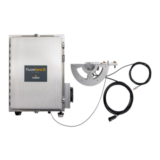
4. Overview 4.1 FluoreSENS 10 system components Figure 4-1. FluoreSENS 10 with fiber guide NOTE: The thick cable with a 5-pin connector provides power to the motor. The thin cable is for the encoder. 4.1.1 FluoreSENS 10 system enclosure The enclosure includes several components: a power supply, TEC, data logger, and spectrometer (s)*. - Page 10 Figure 4-2. FluoreSENS 10 enclosure FluoreSENS 10...
- Page 11 Figure 4-3. FluoreSENS 10 with QE Pro and Flame-T spectrometers Figure 4-4. Bottom of enclosure FluoreSENS 10...
-
Page 12: Spectrometer(S)
Figure 4-5. Flame-T spectometer 4.1.3 CR1000KD The CR1000KD is a portable keyboard and display screen for Campbell Scientific data loggers that have a CSI/O port. It allows for a better user experience while calibrating the spectrometers. 4.1.4 TEC To reduce thermal noise and optimize performance, it is necessary for the CCDs (charge-coupled devices) of spectrometers to operate at subzero temperatures. -
Page 13: Fiber Optic Cable Guide
Figure 4-6. FluoreSENS 10 with spectrometer enclosure cover on 4.1.5 Fiber optic cable guide The wire guide includes a motor and an encoder, which together enable a 180-degree rotation. This rotation allows the wire guide to point upward toward the sky and downward toward vegetation, capturing radiation signals from each direction. -
Page 14: Specifications
(pointing directly upward) and vegetation (pointing directly downward) positions. 5. Specifications 5.1 QE Pro Table 5-1: Spectral characteristics of QE Pro (Ocean Insight spectrometer) in FluoreSENS 10 Optical parameter Value Description... -
Page 15: Power And Temperature Specifications
Total power consumption: 130 W at 25 °C to 150 W at 50 °C Operating temperature range: 0 to 50 °C 5.4 System enclosure weight and dimensions Weight: ~50 lbs Dimensions: 24 in × 20 in × 10 in (60.96 cm × 50.8 cm × 25.4 cm) FluoreSENS 10... -
Page 16: Installation
Figure 6-1. FluoreSENS 10 system mounted on a tripod (tripod and cross-arms are sold separately) The following tools are required to install a FluoreSENS 10 system in the field. Additional tools may be required for a user-supplied tripod or tower. -
Page 17: Mounting And Wiring
Zip ties 6.1 Mounting and wiring 6.1.1 FluoreSENS 10 enclosure While the temperature inside the enclosure is regulated by the TEC, it is strongly advised that the enclosure be installed in a shaded area. Even though the TEC helps to control the internal temperature, external factors such as direct sunlight can still impact overall thermal conditions. -
Page 18: Fluoresens 10 Power, Motor, And Fiber Optic Cable
(a) guide assembly facing down, and (b) guide assembly facing up. 6.1.3 FluoreSENS 10 power, motor, and fiber optic cable Follow the steps below to power the system with main AC power, connect the fiber guide assembly (power and motor cables) to the enclosure, and connect the fiber optic cable(s). -
Page 19: Attach Drip Pan And Insect Screen
Place the drip pan below the TEC fan inside of the enclosure, insert the pipe from the bottom of enclosure and screw onto the drip pan, as shown in Figure 6-3 [p. 15]. Then, attach the screen onto the pipe. This setup will prevent moisture build up inside the enclosure. FluoreSENS 10... -
Page 20: Instrument Height
Table 6-1: Wire color, function, and data logger connection Wire color Wire function Data logger connection White SDI-12 signal Clear Shield Power Black Power ground FluoreSENS 10... -
Page 21: Grounding
It is essential to earth ground both the fiber guide assembly and the enclosure. Grounding wire comes with the purchase of the FluoreSENS 10 and should connect the fiber guide assembly to the grounding lug located at the bottom of the FluoreSENS 10 main enclosure. -
Page 22: Operation
8.2 Field of view The fore optics in FluoreSENS 10 is a cosine corrector that has a field of view of 180 degrees. The use of cosine corrector instead of bare fiber for sampling outgoing irradiance from vegetation ensures good overlap of SIF and flux footprint print. -
Page 23: Wavelength Calibration
NOTE: While absolute irradiance calibration can be carried out in both field and laboratory settings, it is advisable to conduct it in a laboratory setting before the initial deployment of the FluoreSENS 10... -
Page 24: Absolute Irradiance Calibration And Manual Dark Current Measurement Using Rtmc
FluoreSENS 10 operations: (a) radiometric calibration, (b) manual dark sampling and (c) Real time monitoring of SIF signal The FluoreSENS 10 RTMC panel displays useful data from the data logger. For example, the data loggers built-in web pages, which display data logger health and program statistics, such as panel temperature, battery voltage, and program run-time errors, can be accessed through RTMC. - Page 25 6. The system will measure 50 samples. The integration time for each sample is automatically determined by the program based on the intensity of light. Once calibration is complete, prepare for manual dark measurement. Next, manual dark sampling is performed. FluoreSENS 10...
-
Page 26: Irradiance Calibration And Off-Sequence Dark Sampling Using A Cr1000Kd
Within the main menu, utilize the keypad's downward arrow to navigate through the various submenus and options. Select your preferred option and press Enter. If you need to go back to a previous menu, press Esc. Follow the steps below using CR1000KD to perform calibration and dark sampling: FluoreSENS 10... -
Page 27: Manual Dark Sampling Using A Cr1000 Kd
Remove Cover. 3. Remove the cover and switch back to Pause. 4. Attach the fiber optic cable to the fiber guide then switch Operating Model to Run_Sample to start vegetation and sky irradiance measurements. FluoreSENS 10... -
Page 28: Sequence Of Measurement
The data logger internal CPU can only store a small amount of data, so a microSD flash card is recommended with the CR1000X. In some situations, it may also be possible to remotely transmit time series data. For additional information on these options, please contact Campbell Scientific. FluoreSENS 10... -
Page 29: Post Processing
WARNING: Campbell Scientific recommends and supports only the use of microSD cards obtained from Campbell Scientific. These cards are industrial grade and have passed Campbell Scientific hardware quality testing. Use of consumer grade cards substantially increases the risk of data loss. - Page 30 (an .lmp file is provided by the manufacturer, or the coefficients can be found in the lamp calibration data sheet). The pixel-specific count to irradiance conversion factor, b(λ), is determined as: Eq. 4 FluoreSENS 10...
- Page 31 The integrating sphere (cosine corrector) can be removed and placed back on with the calibration remaining valid. However, it would need to be the same model of integrating sphere. FluoreSENS 10...
-
Page 32: Sif Retrieval
Timer starts up on request for spectrum data from QE mSecSinceTrig_QEPro Pro, which determines the elapsed time required to milliseconds get the spectrum measurement 0 — incoming irradiance measurement (sky) IMACSSCode 1 — outgoing radiance measurement (vegetation) 7 — dark current measurment at night FluoreSENS 10... -
Page 33: Flameveg Data Table, And Flamesky Data Table
CompileOptions is set as True and will have data only if Flame is connected. Table 14-2: FlameVeg, and FlameSky data tables Parameter Description Units TIMESTAMP Time of measurement datetime RECORD Number of data recorded Number of data records that will restart every nEvent time the system boots up MotorFiberFace_Trk Sky or veg FluoreSENS 10... - Page 34 Flame pixel number corresponding to peak PixelMaxV_Bin pixel count Integration_uSec Actual Flame integration time microseconds -1 = Success Flag indicating integration time sent by the SetFlameIntegrationSuccess program was successful 0 = Failed Pixel (22 -3669) Optical active pixels 3648 active pixel FluoreSENS 10...
-
Page 35: Set Up And Measurement Workflow
15. Set up and measurement workflow Set up, calibration, initiation of measurements, and retrieval of SIF can be summarized in the following steps: Mount the FluoreSENS 10 enclosure on the tripod and the fiber guide on the crossarm Mounting and wiring (p. -
Page 36: Vegetation Indices
It is primarily used as an indicator of water stress and for the assessment of carbon-dioxide uptake by plants. Eq. 8 Other vegetation indices can also be calculated as needed from combinations of surface reflectance between 350 and 1000 nm. FluoreSENS 10... -
Page 37: Troubleshooting And Maintenance
In such scenarios, the fiber guide should be accurately positioned using RTMC/CR1000KD and the home preset button in the AZD-KD (see FluoreSENS 10 enclosure (p. 5) for more details). 1. Bring the System Mode to Pause. Wait for the current sampling to complete and System Status Message to change to Paused: SetRunToStart. -
Page 38: Flame And Sn500 Tables With No Output
The motor errors that cannot be reset by the datalogger program are: Const Mtr_Err 20h = 32 Over Current Const Mtr_Err 28h = 40 Sensor Error - check motor connection /pwr cycle Const Mtr_Err 2Ah = 42 ABZO Sensor communication error - check Encoder Cbl /pwr cycle FluoreSENS 10... -
Page 39: Removing And Reconnecting Spectrometer(S)
4. Detach the power connector and disconnect the 30-pin connector (ribbon cable to the logger). Follow the sequence below for reattaching the spectrometer(s): 1. Turn off the AC power supply and safely detach the 12V battery terminals to power down the system. FluoreSENS 10... -
Page 40: Cardstatus Error After Setting Sn500 In Compileoptions To True
17.6 CardStatus error after setting SN500 in CompileOptions to true If an SN500 is added to the FluoreSENS 10 system at a later date, CompileOptions associated with this sensor will need to be set true to output the SN500 table. Following this step, you may encounter a ‘Data on Cards is from a different program or is corrupted’... -
Page 41: Pc400
19.1 Silica desiccant bags Silica desiccant bags (Figure 19-1 [p. 36]) are used to desiccate the system enclosure and should be periodically replaced. These can be purchased in packs of 1, 4, or 20. Figure 19-1. Single desiccant pack FluoreSENS 10... -
Page 42: Humidity Indicator Card
20. Licensed materials Statement of Licensed Materials Some of the technologies employed by FluoreSENS 10 are licensed materials. This technology acquired under license from UT-Battelle, LLC, the management and operating contractor of the Oak Ridge National Laboratory acting on behalf of the U.S. Department of Energy under Contract No. -
Page 43: References
Chang, C. Y., L. Guanter, C. Frankenberg, P. Köhler, L. Gu, T. S. Magney, K. Grossmann, and Y. Sun. 2020. Systematic assessment of retrieval methods for canopy far-red solar-induced chlorophyll fluorescence using high-frequency automated field spectroscopy. Journal of Geophysical Research: Biogeosciences 125(7), e2019JG005533. FluoreSENS 10... - Page 44 2. The defect cannot be the result of misuse. 3. The defect must have occurred within a specified period of time; and 4. The determination must be made by a qualified technician at a Campbell Scientific Service Center/ repair facility.
- Page 45 Campbell Scientific’s Terms, the provisions of Campbell Scientific’s Terms shall prevail. Furthermore, Campbell Scientific’s Terms are hereby incorporated by reference into this Warranty. To view Terms and conditions that apply to Campbell Scientific, Logan, UT, USA, see Terms and Conditions.
- Page 46 Please state the faults as clearly as possible. Quotations for repairs can be given on request. It is the policy of Campbell Scientific to protect the health of its employees and provide a safe working environment. In support of this policy, when equipment is returned to Campbell Scientific, Logan, UT, USA, it is mandatory that a “Declaration of Hazardous Material and...
- Page 47 Comply with all electrical codes. Electrical equipment and related grounding devices should be installed by a licensed and qualified electrician. Only use power sources approved for use in the country of installation to power Campbell Scientific devices. Elevated Work and Weather Exercise extreme caution when performing elevated work.
- Page 48 Periodically (at least yearly) check electrical ground connections. WHILE EVERY ATTEMPT IS MADE TO EMBODY THE HIGHEST DEGREE OF SAFETY IN ALL CAMPBELL SCIENTIFIC PRODUCTS, THE CUSTOMER ASSUMES ALL RISK FROM ANY INJURY RESULTING FROM IMPROPER INSTALLATION, USE, OR MAINTENANCE OF TRIPODS, TOWERS, OR ATTACHMENTS TO TRIPODS...
- Page 49 Campbell Scientific Regional Offices Australia France Thailand Location: Garbutt, QLD Australia Location: Montrouge, France Location: Bangkok, Thailand Phone: 61.7.4401.7700 Phone: 0033.0.1.56.45.15.20 Phone: 66.2.719.3399 Email: info@campbellsci.com.au Email: info@campbellsci.fr Email: info@campbellsci.asia Website: www.campbellsci.com.au Website: www.campbellsci.fr Website: www.campbellsci.asia Brazil Germany Location: São Paulo, SP Brazil...
Need help?
Do you have a question about the FluoreSENS 10 and is the answer not in the manual?
Questions and answers