Campbell CNR4 Instruction Manual
Net radiometer
Hide thumbs
Also See for CNR4:
- Instruction manual (70 pages) ,
- User manual (60 pages) ,
- Product manual (52 pages)

Related Manuals for Campbell CNR4


Summary of Contents for Campbell CNR4
- Page 1 CNR4 Net Radiometer Revision: 11/10 C o p y r i g h t © 2 0 0 0 - 2 0 1 0 C a m p b e l l S c i e n t i f i c ,...
- Page 2 Warranty and Assistance The CNR4 NET RADIOMETER is warranted by Campbell Scientific, Inc. to be free from defects in materials and workmanship under normal use and service for twelve (12) months from date of shipment unless specified otherwise. Batteries have no warranty. Campbell Scientific, Inc.'s obligation under this warranty is limited to repairing or replacing (at Campbell Scientific, Inc.'s option) defective products.
-
Page 3: Table Of Contents
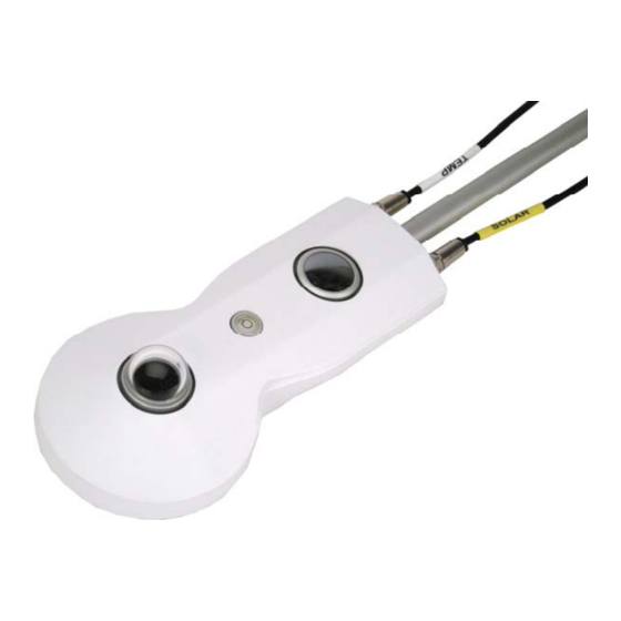
2.4.1 CNF4 Specifications ...............6 3. Installation..............6 4. Using the Optional CNF4 Heater/Ventilator Unit..8 5. Using the CNR4 in the Four Separate Components Mode ................9 5.1 Measuring Short-wave Solar Radiation with Pyranometer ......9 5.2 Measuring Long-wave Far Infrared Radiation with Pyrgeometer ....9 5.3 Measuring CNR4 Temperature with Thermistor ........10... - Page 4 ............ 8 6-1. The CNR4 sensor with SOLAR and TEMP cables ......14 6-2. The marks on the end of the CNR4: S for SOLAR cable, and T for TEMP cable..................15 6-3. Labels on the pigtail end of the SOLAR cable ........15 6-4.
- Page 5 CNR4 Table of Contents Tables 5-1. Resistance values versus CNR4's thermistor temperature in °C ...11 5-2. Resistance values versus CNR4's Pt-100 temperature in °C ....12 6-1. Datalogger Connections for Differential Measurement ......16 6-2. Datalogger Connections for Single-ended Measurement......16 A-1. Typical output signals of CNR4 under different meteorological conditions.
- Page 6 CNR4 Table of Contents...
-
Page 7: General Description
The CNR4 design is very light in weight and has an integrated solar shield that reduces thermal effects on both the short-wave and the long-wave measurements. -
Page 8: Sensor Specifications
CNF4-L is available. See Appendix B for more information on the CNF4-L. The properties of the CNR4 are mainly determined by the properties of the individual probes. Generally the accuracy of the CNR4 will be higher than that of competitive net-radiometers, because the solar radiation measurement performed by the pyranometer is accurate, and offers a traceable calibration. -
Page 9: Cnr4 Specifications
CNR4 Net Radiometer 2.1 CNR4 Specifications Sensor sensitivities: Four probes have unique sensitivity values. Please refer to the calibration sheets or label on the bottom of the sensor for the sensitivity values. Operating temperature: -40 to +80°C (-40 to 176°F) -
Page 10: Pyranometer Specifications
CNR4 Net Radiometer 2.2 Pyranometer Specifications * indicates ISO specifications. Spectral range: 305 to 2800 nm (50% points) Sensitivity: 10 to 20 µV/W/m < 18 seconds (95% response) Response time*: Non-linearity*: < 1% (0-1000 W m irradiance) Non-stability*: < 1%... -
Page 11: Pyrgeometer Specifications
CNR4 Net Radiometer 2.3 Pyrgeometer Specifications Spectral range: 4.5 μm to 42 μm (50% points) Sensitivity: 5 to 15 μV/W/m Impedance: 20 Ω to 200 Ω (typically 50) < 18 seconds (95% response) Response time: Non-linearity: < 1% (-250 to +250 W/m... -
Page 12: Cnf4 Specifications
Northern Hemisphere this implies that the net radiometer should be mounted on the south side of the mast. It is suggested that the CNR4 is mounted at a height of at least 1.5 meters above the surface to avoid shading effects of the instruments on the soil and to promote spatial averaging of the measurement. -
Page 13: Attaching The Mounting Rod To The Cnr4 Body
Perform the fine levelling using the two spring-loaded levelling screws: one on the front and the other on the back of the bracket. FIGURE 3-1. Attaching the mounting rod to the CNR4 body. -
Page 14: Using The Optional Cnf4 Heater/Ventilator Unit
For installation in buildings or in solar energy applications, one will often have to mount the CNR4 parallel to the surface that is being studied. This may be in a tilted or a vertical position. The sensitivity of the radiometers will be affected, but only in a minor way. -
Page 15: Using The Cnr4 In The Four Separate Components Mode
CNR4 Net Radiometer 5. Using the CNR4 in the Four Separate Components Mode In the four separate components mode configuration (measuring two short- wave radiation signals, two long-wave signals), all signals are measured separately. Calculation of net-radiation and albedo can be done on-line by the datalogger, or off-line by the user during post-processing, using the stored raw data. -
Page 16: Measuring Cnr4 Temperature With Thermistor
T, into account. This is why the temperature sensors are incorporated in the CNR4's body near the pyrgeometer sensing element, and has, therefore, the same temperature as the pyrgeometer sensor surface. -
Page 17: Resistance Values Versus Cnr4'S Thermistor Temperature In °C
In order to make the temperature measurement, using the Pt-100 sensor, you will need one current excitation channel, and one differential analog channel. Please refer to Appendix C for a sample program to measure Pt-100. TABLE 5-1. Resistance values versus CNR4's thermistor temperature in °C. Temperature Resistance... -
Page 18: Calculation Of Albedo
CNR4 Net Radiometer TABLE 5-2. Resistance values versus CNR4's Pt-100 temperature in °C. Temperature Resistance Temperature Resistance Temperature Resistance [°C] [°C] [°C] [Ω] [Ω] [Ω] 88.22 100.00 111.67 88.62 100.39 112.06 89.01 100.78 112.45 89.40 101.17 112.83 89.80 101.56 113.22 90.19... -
Page 19: Calculation Of Net Short-Wave Radiation
Therefore, if one is only interested in the net long-wave radiation, instead of separate upper and lower components of the long-wave radiation, the CNR4 temperature measurement is not required. The E measured with the pyrgeometer actually represents the irradiance of the sky (for upward- facing pyrgeometer) or the ground (for downward-facing pyrgeometer). -
Page 20: Calculation Of Net (Total) Radiation
CNR4. The wiring diagrams for the thermistor in this manual is applicable only if the CNR4 and the cables were purchased from Campbell Scientific, Inc. -
Page 21: The Marks On The End Of The Cnr4: S For Solar Cable, And T For Temp Cable
CNR4 Net Radiometer FIGURE 6-2. The marks on the end of the CNR4: S for SOLAR cable, and T for TEMP cable. The measurement details for Pt-100 sensor, including the wiring diagram and sample program are explained in the Appendix C of this manual. -
Page 22: Labels On The Pigtail End Of The Temp Cable
CNR4 Net Radiometer FIGURE 6-4. Labels on the pigtail end of the TEMP cable. TABLE 6-1. Datalogger Connections for Differential Measurement Function Wire Color CR1000 CR3000/CR5000 Pyranometer Up Signal Differential Input (H) Differential Input (H) Pyranometer Up Reference *Blue Differential Input (L) -
Page 23: Datalogger Programming
CNR4 Net Radiometer 7. Datalogger Programming The CNR4 outputs four voltages that typically range from 0 to 15 mV for the pyranometers, and ± 5 mV for the pyrgeometers. A differential voltage measurement is recommended because it has better noise rejection than a single-ended measurement. - Page 24 'CNR4 program 'This program measures CNR4 four-component net radiometer 'This program also measures the thermistor inside the CNR4 'User must enter the sensitivity values for all four probes in the program and save/compile 'prior to downloading it to the datalogger.
- Page 25 Units albedo = W/m^2 Units Rn = W/m^2 Dim Rs, Vs_Vx 'CNR4 sensitivities: refer to the Certificate of Calibration from Kipp & Zonen for sensitivity values 'for each probes, and enter them below. Const pyranometer_up_sensitivity = 15.35 'unique sensitivity for upper pyranometer '(microV/W/m^2) Const pyranometer_dn_sensitivity = 15.41...
- Page 26 EndTable DataTable (cnr4_ts,True,-1) DataInterval (0,1,Sec,10) CardOut (1,-1) Sample (4,cnr4(1),IEEE4) Sample (1,cnr4_T_K,IEEE4) EndTable BeginProg 'Load the multiplier values for the CNR4 cnr4_mult(1) = pyranometer_up_mult cnr4_mult(2) = pyranometer_dn_mult cnr4_mult(3) = pyrgeometer_up_mult cnr4_mult(4) = pyrgeometer_dn_mult Scan (1,Sec,3,0) PanelTemp (logger_temp,250) Battery (batt_volt) 'CNR4 radiation measurements...
-
Page 27: Example 2, Cr3000 Program Using Differential Measurements
60 minutes. It also stores the raw time-series data from CNR4 to data table called cnr4_ts. Minimum Battery voltage... - Page 28 Units albedo = W/m^2 Units Rn = W/m^2 Dim Rs, Vs_Vx 'CNR4 sensitivities: refer to the Certificate of Calibration from Kipp & Zonen for sensitivity values 'for each probes, and enter them below. Const pyranometer_up_sensitivity = 15.35 'unique sensitivity for upper pyranometer '(microV/W/m^2) Const pyranometer_dn_sensitivity = 15.41...
- Page 29 EndTable DataTable (cnr4_ts,True,-1) DataInterval (0,1,Sec,10) CardOut (1,-1) Sample (4,cnr4(1),IEEE4) Sample (1,cnr4_T_K,IEEE4) EndTable BeginProg 'Load the multiplier values for the CNR4 cnr4_mult(1) = pyranometer_up_mult cnr4_mult(2) = pyranometer_dn_mult cnr4_mult(3) = pyrgeometer_up_mult cnr4_mult(4) = pyrgeometer_dn_mult Scan (1,Sec,3,0) PanelTemp (logger_temp,250) Battery (batt_volt) 'CNR4 radiation measurements...
-
Page 30: Example 3, Cr5000 Program Using Differential Measurements
60 minutes. It also stores the raw time-series data from CNR4 to data table called cnr4_ts. NOTE The variables for the CR5000 datalogger can be up to 16 characters in length. - Page 31 'CNR4 program 'This program measures CNR4 four-component net radiometer 'This program also measures the thermistor inside the CNR4 'User must enter the sensitivity values for all four probes in the program and save/compile 'prior to downloading it to the datalogger.
- Page 32 Units albedo = W/m^2 Units Rn = W/m^2 Dim Rs, Vs_Vx 'CNR4 sensitivities: refer to the Certificate of Calibration from Kipp & Zonen for sensitivity values 'for each probes, and enter them below. Const pyra_up_sensitiv = 15.35 'unique sensitivity for upper pyranometer (microV/W/m^2) Const pyra_dn_sensitiv = 15.41...
- Page 33 CNR4 Net Radiometer DataTable (cnr4_ts,True,-1) DataInterval (0,1,Sec,10) CardOut (1,-1) Sample (4,cnr4(1),IEEE4) Sample (1,cnr4_T_K,IEEE4) EndTable BeginProg 'Load the multiplier values for the CNR4 cnr4_mult(1) = pyra_up_mult cnr4_mult(2) = pyra_dn_mult cnr4_mult(3) = pyrg_up_mult cnr4_mult(4) = pyrg_dn_mult Scan (1,Sec,3,0) PanelTemp (logger_temp,250) Battery (batt_volt)
-
Page 34: Troubleshooting
CNR4 Net Radiometer 8. Troubleshooting If there is no indication as to what may be the problem, start performing the following "upside-down test", which is a rough test for a first diagnosis. It can be performed both outdoors and indoors. Indoors, a lamp can be used as a source for both short-wave and long-wave radiation. -
Page 35: Testing The Pyrgeometer
It is assumed that the zero offset is no more than a few watts per square meter (see second test in section 8.1). The CNR4 body and the ambient air should be at the same temperature as much as possible. Let the pyrgeometer rest for at least five minutes to regain its thermal equilibrium. -
Page 36: Recalibration
Please contact Campbell Scientific to obtain an RMA number for recalibration. 9.3 Replacing the Drying Cartridge The CNR4 has a drying cartridge inside the sensor to help keep the electronics dry. The manufacturer recommends that this drying cartridge be replaced every 6 to 12 months. -
Page 37: Replacement Parts
CNR4 Net Radiometer 9.4 Replacement Parts The following is the list of replacement parts for the CNR4 and CNF4 (heater/ventilator) available from Campbell Scientific. CSI Part Number Description CNR4CBL1-L Replacement CNR4 Solar Cable CNR4CBL2-L Replacement CNR4 Temperature Cable CNF4CBL-L Replacement CNF4 Cable... - Page 38 CNR4 Net Radiometer...
-
Page 39: A. Cnr4 Performance And Measurements Under Different Conditions
This can roughly be attributed to the water vapor in the air, which is a major contributor to the far infrared radiation. TABLE A-1. Typical output signals of CNR4 under different meteorological conditions. Explanation can be found in the text. -
Page 40: Cnr4 Performance And Measurements Under Different Conditions
Appendix A. CNR4 Performance and Measurements under Different Conditions FIGURE A-1. Different measurement conditions and signals. Upper pyrgeometer Day with alternating cloud fields pyrgeometer: U_emf / Sensitivity [W/m²] Temp YSI 44031 [°C] ‐10 ‐20 ‐30 ‐40 ‐50 ‐60 ‐70 ‐80 ‐90 ‐100 ‐110 ‐120 ‐130 ‐140 ‐150 ‐160 ‐170 ‐180 FIGURE A-2. Partly cloudy day for the upward facing pyrgeometer. -
Page 41: A-3. Clear Day For The Downward Facing Pyrgeometer
Appendix A. CNR4 Performance and Measurements under Different Conditions upwelling signal (downward facing) pyrgeometer Pyrgeometer: U‐emf / sensitivity [W/m²] Temp of instrument [°C] ‐10 ‐20 ‐30 FIGURE A-3. Clear day for the downward facing pyrgeometer. It is assumed that when ambient temperature varies, the net far infrared radiation remains roughly the same, independent of ambient temperature. The resulting measured values of the pyrgeometers and pyranometers are shown in columns 4 to 7. - Page 42 Appendix A. CNR4 Performance and Measurements under Different Conditions ⎡ ⎤ upper Sky temper ature ⎢ ⎥ − ⎣ ⋅ ⎦ (B-1) ⎡ ⎤ lower Ground Temperatur ⎢ ⎥ − ⋅ ⎣ ⎦ (B-2)
-
Page 43: Cnf4 Heater/Ventilator
Appendix B. CNF4 Heater/Ventilator NOTE Whenever the heater is used, the heating may cause errors in the measurement of the sensor temperature. Under most conditions the accuracy that is gained by heating will be larger than the errors that are introduced by heating. In both the pyranometer and the pyrgeometer, thermal sensors are used, and these sensors in principle measure a heat flow. - Page 44 1 hour after the sunrise. The heater power can be controlled using one of the SW12V channels of the Campbell Scientific dataloggers. The heater’s current drain is approximately 850 mA at 12 Vdc (10 Watts). The ventilator draws additional 5 Watts of power at 12 Vdc.
-
Page 45: Attaching The Optional Cnf4 Heater/Ventilator Unit To Cnr4
Appendix B. CNF4 Heater/Ventilator B.2 Attaching the Optional CNF4 Heater/Ventilator Unit to CNR4 1. The CNF4 heater/ventilator unit comes with the following: the heater/ventilator, the white solar shield, three pan-head screws with washers, and four flat-head screws as shown in Figure B-1. -
Page 46: B-2. Attaching The Cnf4 To Cnr4 Using Pan-Head Screws And Washers
Appendix B. CNF4 Heater/Ventilator 2. Attach the heater/ventilator unit unto the bottom of the CNR4 sensor, using the three pan-head screws and washers, as shown in Figure B-2. Make sure that the pyranometer and the pyrgeometer windows are not scratched during the installation. -
Page 47: B-3. Making Sure The Cables Are Clear From The Edges
Appendix B. CNF4 Heater/Ventilator 3. Make sure the cables are cleared from the edges of the CNF4, as shown in Figure B-3, and place the white solar shield over it. Use the four flat-head screws provided to complete the solar shield installation to the CNF4, as shown in Figure B-4 and B-5. -
Page 48: B-5. Attaching The Solar Shield To Cnf4 Using Four Flat-Head Screws
4. Once the CNF4 heater/ventilator unit is attached to the bottom side of the CNR4, the CNF4 will cover the label that contains the serial number and the sensitivity values for the four sensors. Affix the extra label that came with the sensor to the bottom side of the CNF4’s anodized aluminium base... -
Page 49: B.3 Wiring
Appendix B. CNF4 Heater/Ventilator B.3 Wiring The following table shows the recommended datalogger wiring for using the CNR4 sensor with the CNF4 heater/ventilator while making the differential measurement. TABLE B-1. CR1000 and CR3000 Datalogger Connections for Differential Measurement with Heater/Ventilator Control... -
Page 50: Example B, Cr3000 Datalogger Program With Heater/Ventilator Control
'CR3000 Series Datalogger 'CNR4 program 'This program measures CNR4 four-component net radiometer 'This program also measures the thermistor inside the CNR4 'In addition this program controls heater and ventilator ' using separate SW12V-1 and SW12V-2 channels 'The heater and ventilator are turned on/off by setting flag(1), and flag(2) high and low, respectively. - Page 51 Appendix B. CNF4 Heater/Ventilator CNR4 thermistor signal (white) 'gnd CNR4 thermistor signal reference (black) CNR4 thermistor shield (clear) 'VOLTAGE EXCITATION 'VX1 CNR4 thermistor voltage excitation (red) 'POWER OUT 'SW12V-1 CNF4 ventilator + (red) 'SW12V-2 CNF4 heater + (green) CNF4 ventilator - (blue)
- Page 52 Appendix B. CNF4 Heater/Ventilator Dim Rs, Vs_Vx 'CNR4 sensitivities: refer to the Certificate of Calibration from Kipp & Zonen for sensitivity values 'for each probes, and enter them below. Const pyranometer_up_sensitivity = 15.35 'unique sensitivity for upper pyranometer '(microV/W/m^2) Const pyranometer_dn_sensitivity = 15.41...
-
Page 53: B.5 Cnf4 Heater/Ventilator Maintenance
Appendix B. CNF4 Heater/Ventilator 'CNR4 thermistor measurement BrHalf (Vs_Vx,1,mv5000,16,Vx1,1,2500,True ,0,250,1.0,0) Rs = 1000*(Vs_Vx/(1-Vs_Vx)) cnr4_T_C = 1/(1.0295e-3+2.391e-4*LN(Rs)+1.568e-7*(LN(Rs))^3)-273.15 'Convert CNR4 temperature to Kelvin cnr4_T_K = cnr4_T_C+273.15 'Correct the long-wave radiation values from pyrgeometers long_up_corr = long_up+5.67e-8*cnr4_T_K^4 long_dn_corr = long_dn+5.67e-8*cnr4_T_K^4 'Compute short-wave net radiation... -
Page 54: Replacing The Filter For The Ventilator
The filter can be cleaned with warm clean water, or can be replaced with the new one. You can purchase the replacement filters from Campbell Scientific (CSI p/n 26010, a set of 5). -
Page 55: Cr3000 Program For Measuring Pt-100
Measuring Pt-100 Temperature Sensor The program example C measures the Pt-100 sensor for the body temperature of the CNR4. This program requires four differential channels to measure the four radiation outputs, and one current excitation channel and one differential channel for Pt-100 measurement. The program measures the sensors every 1 second, performs the on-line processing of the data and stores the following processed data to a data table called cnr4_data once every 60 minutes. - Page 56 'CNR4 program 'This program measures CNR4 four-component net radiometer 'This program also measures the Pt-100 sensor inside the CNR4 'User must enter the sensitivity values for all four probes in the program and save/compile 'prior to downloading it to the datalogger.
- Page 57 Units albedo = W/m^2 Units Rn = W/m^2 Dim cnr4_prt_R, Rs_R0 'CNR4 sensitivities: refer to the Certificate of Calibration from Kipp & Zonen for sensitivity values 'for each probes, and enter them below. Const pyranometer_up_sensitivity = 15.35 'unique sensitivity for upper pyranometer '(microV/W/m^2) Const pyranometer_dn_sensitivity = 15.41...
- Page 58 EndTable DataTable (cnr4_ts,True,-1) DataInterval (0,1,Sec,10) CardOut (1,-1) Sample (4,cnr4(1),IEEE4) Sample (1,cnr4_T_K,IEEE4) EndTable BeginProg 'Load the multiplier values for the CNR4 cnr4_mult(1) = pyranometer_up_mult cnr4_mult(2) = pyranometer_dn_mult cnr4_mult(3) = pyrgeometer_up_mult cnr4_mult(4) = pyrgeometer_dn_mult Scan (1,Sec,3,0) PanelTemp (logger_temp,250) Battery (batt_volt) 'CNR4 radiation measurements...
- Page 60 Campbell Scientific Companies Campbell Scientific, Inc. (CSI) 815 West 1800 North Logan, Utah 84321 UNITED STATES www.campbellsci.com • info@campbellsci.com Campbell Scientific Africa Pty. Ltd. (CSAf) PO Box 2450 Somerset West 7129 SOUTH AFRICA www.csafrica.co.za • cleroux@csafrica.co.za Campbell Scientific Australia Pty. Ltd. (CSA)
Need help?
Do you have a question about the CNR4 and is the answer not in the manual?
Questions and answers