
Related Manuals for Campbell 27106T


Summary of Contents for Campbell 27106T
- Page 1 27106T Gill Propeller Anemometer Revision: 2/11 C o p y r i g h t © 1 9 8 4 - 2 0 1 1 C a m p b e l l S c i e n t i f i c ,...
- Page 3 PLEASE READ FIRST About this manual Please note that this manual was originally produced by Campbell Scientific Inc. (CSI) primarily for the US market. Some spellings, weights and measures may reflect this origin. Some useful conversion factors: 1 in (square inch) = 645 mm Area: 1 in.
- Page 4 7. Troubleshooting ............10 8. References ..............10 Figures 3-1. 27106T Mounted to a Crossarm via the CM220 ........4 3-2. 27106T Mounted to a Crossarm via a NU-RAIL Fitting ......4 Tables 1-1. Recommended Lead Lengths ..............1 4-1. Connections to Campbell Scientific Dataloggers ........5 5-1.
-
Page 6: General Description
The R.M. Young Instruction Manual includes additional information on the operating principles, installation and maintenance of the sensor. Lead length for the 27106T is specified when the sensor is ordered. Table 1-1 gives the recommended lead length for mounting the sensor at the top of the tripod/tower with a 019ALU or CM200 series crossarm. -
Page 7: Installation
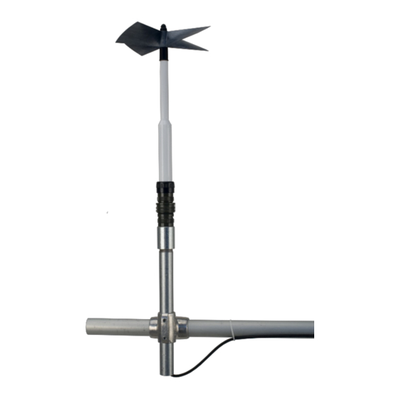
Weight: 1.2 lbs (0.5 kg) *Threshold and Distant Constant values are for axial flows. Manufactured by RM Young (Traverse City, MI) and cabled by Campbell Scientific for use with our dataloggers. ® The black outer jacket of the cable is Santoprene rubber. - Page 8 27106T Gill Propeller Anemometer Once everything has been retrieved from the shipping carton, assemble the 27106T by doing the following: 1. Remove the propeller shaft from the Propeller Anemometer box 2. Remove the propeller from the Carbon Fiber Propeller box 3.
- Page 9 27106T Gill Propeller Anemometer Mounting Pipe CM220 Crossarm FIGURE 3-1. 27106T Mounted to a Crossarm via the CM220 NU-RAIL Crossarm Fitting FIGURE 3-2. 27106T Mounted to a Crossarm via a NU-RAIL Fitting...
- Page 10 5. Programming This section is for users who write their own programs. A datalogger program to measure this sensor can be generated using Campbell Scientific’s Short Cut Program Builder software. You do not need to read this section to use Short Cut software.
-
Page 11: Cr1000 Example Program
UVW configuration with RM YOUNG model 26601UVW Translator. 5.2 Example Programs The following programs measure the 27106T every 1 second, and store the maximum, minimum, and average wind speed every 10 minutes. Wiring for the examples is given in Table 5-2. -
Page 12: Cr10X Example Program
Maximum (1,WS_ms,FP2,False,False) Minimum (1,WS_ms,FP2,0,False) Average (1,WS_ms,FP2,False) EndTable 'Main Program BeginProg Scan (1,Sec,1,0) Battery (Batt_Volt) '27106T Wind Speed Sensor measurement VoltSe (WS_ms,1,mV2500,1,1,0,250,0.01800,0) 'mV5000 range code for CR3000 and CR5000 dataloggers 'Call Output Tables CallTable Table1 NextScan EndProg 5.2.2 CR10X Example Program ;{CR10X}... -
Page 13: Sensor Maintenance
This replacement procedure needs to be done by a CAUTION qualified technician. If a qualified technician is not available, return the sensor to Campbell Scientific and have their qualified technicians replace the bearing. Refer to the Warranty and Assistance page for more information. NOTE This replacement procedure is from RM Young Operation manual (see Section 8). - Page 14 This replacement procedure needs to be done by a qualified technician. If a qualified technician is not available, return the sensor to Campbell Scientific and have their qualified technicians replace the Tach- Generator. Refer to the Warranty and Assistance page for more information.
-
Page 15: Troubleshooting
27106T Gill Propeller Anemometer Replace the tach-generator as follows: REMOVE OLD GENERATOR ASSEMBLY a) Remove propeller from anemometer. b) Unthread generator housing collar. Pull generator housing away from sensor connector and generator assembly. c) Note position of generator wires on sensor connector pins. Unsolder wires from pins and remove old generator assembly. - Page 16 27106T Gill Propeller Anemometer Drinkow, R., “A Solution to the Paired Gill-Anemometer Response Function”, Journal of Applied Meteorology, Vol 11, 1972, pp. 7-80. Hicks, B. B., “Propeller Anemometers as Sensors of Atmospheric Turbulence”, Boundary-Layer Meteorology, Vol 3, 1972, pp. 214-228 Fichtl, G.
- Page 17 27106T Gill Propeller Anemometer...
-
Page 19: Campbell Scientific Companies
Campbell Scientific Companies Campbell Scientific, Inc. (CSI) 815 West 1800 North Logan, Utah 84321 UNITED STATES www.campbellsci.com • info@campbellsci.com Campbell Scientific Africa Pty. Ltd. (CSAf) PO Box 2450 Somerset West 7129 SOUTH AFRICA www.csafrica.co.za • cleroux@csafrica.co.za Campbell Scientific Australia Pty. Ltd. (CSA)
Need help?
Do you have a question about the 27106T and is the answer not in the manual?
Questions and answers