Table of Contents

Related Manuals for Campbell EC155


Summary of Contents for Campbell EC155
- Page 1 EC155 and H Closed-Path Gas Analyzer and EC100 Electronics with Optional CSAT3A 3D Sonic Anemometer User Manual Issued 25.3.13 © Copyright 2010-2013 Campbell Scientific Inc. Printed under licence by Campbell Scientific Ltd. CSL 905...
- Page 3 Quotations for repairs can be given on request. It is the policy of Campbell Scientific to protect the health of its employees and provide a safe working environment, in support of this policy a “Declaration of Hazardous Material and Decontamination”...
-
Page 5: About This Manual
PLEASE READ FIRST About this manual Please note that this manual was originally produced by Campbell Scientific Inc. primarily for the North American market. Some spellings, weights and measures may reflect this origin. Some useful conversion factors: Area: 1 in... -
Page 7: Table Of Contents
Contents PDF viewers note: These page numbers refer to the printed version of this document. Use the Adobe Acrobat® bookmarks tab for links to specific sections. 1. Introduction ..............1 2. Cautionary Statements ..........1 3. Initial Inspection ............2 4. - Page 8 C.2 Decarbite MSDS ..................2 Figures 5-1. Dimensions of EC155 Analyzer Head with Optional Heated Intake ..7 5-2. Dimensions of EC155 Analyzer Head without Optional Heated Intake . 7 6-1. Exploded view of mounting the EC155 Gas Analyzer and the CSAT3A Sonic Head ................
- Page 9 A to position B, thus freeing the struts of the analyzer ................... 27 9-4. The EC155 Analyzer and Sample Cell with shell top open ....27 9-5. Analyzer removed from sample cell and shell ........28 9-6.
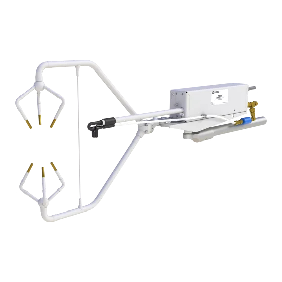
- Page 11 EC155 should look like one of the photographs below, depending on the sample cell option ordered. After unpacking, it is recommended to save the foam cutout as the EC155 components should be placed in the foam cutout whenever the EC155 is transported to another location.
-
Page 13: Introduction
• WARNING: Do not carry the EC155 or CSAT3A by the arms or carry the EC155 by the strut between the arms. Always hold them by the block, where the upper and lower arms connect. Handle the EC155 carefully. The optical source may be damaged by rough handling, especially while the analyzer is powered. -
Page 14: Initial Inspection
4.8 W power; it has minimal spatial displacement from the sample volume of a CSAT3A sonic anemometer; the EC100 electronics synchronize data from the EC155 and CSAT3A; and the analyzer is easily integrated into the CPEC200 closed-path eddy covariance system, a turn-key system containing data acquisition and control instrumentation, a sample pump, and optional zero-and-span valve module. -
Page 15: Specifications
5. Specifications 5.1 Measurements Features • To compute carbon dioxide, water vapour, and sensible heat fluxes using the eddy-covariance method, the EC155 measures: absolute carbon dioxide water vapour mixing ratios three-dimensional wind speed (requires CSAT3A) sonic air temperature (requires CSAT3A) sample cell temperature barometric pressure. - Page 16 EC155 CO and H O Closed-Path Gas Analyzer and EC100 Electronics with Optional CSAT3A 3D Sonic Anemometer O performance ±0.037 g·m (±0.05 mmol·mol ·°C ·°C Zero max drift ±0.3% of reading·°C (maximum) Gain Drift: ±0.05 mol H O·mol (maximum) Sensitivity to CO CSAT3A sonic measurement precision 1 mm·s...
-
Page 17: Output Signals
O mixing ratio equation: mmol/mol = 11.31 (V ) – 3.04 -3 to 53 mmol/mol Full scale range: Synchronous Device for Measurement. A Campbell Scientific, Inc. proprietary serial interface for datalogger to peripheral and sensor communication. See Section 8.1, SDM Output for details. -
Page 18: Physical Description
12.0 cm (4.72 in) Sample cell length: 7.94 mm (0.313 in) Sample cell diameter: Spatial separation between EC155 optional intake and 15 cm (6.0 in) CSAT3A sample volume: Length of tubing from tip of optional heated intake 58.4 cm (23 in) to sample cell: Inside diameter of intake tubing: 2.67 mm (0.105 in) -
Page 19: Dimensions Of Ec155 Analyzer Head With Optional Heated Intake
User Manual Figure 5-1. Dimensions of EC155 analyzer head with optional heated intake Figure 5-2. Dimensions of EC155 analyzer head without optional heated intake... -
Page 20: Power Requirements
6. Installation 6.1 Mounting The EC155 is supplied with mounting hardware to attach it to the end of a horizontal pipe of 1.31 inch outer diameter, such as the CM202, CM204, or CM206 crossarm (p/n #1790x). The EC155 mounting hardware also accommodates an optional CSAT3A sonic anemometer, placing it at the proper position when the EC155 is configured with the optional heated intake assembly. -
Page 21: Dimensions Of Ec155 Analyzer Head Without Optional Heated Intake . 7 6-1. Exploded View Of Mounting The Ec155 Gas Analyzer And The Csat3A Sonic Head
CSAT3A Sonic Anemometer Head EC155 Gas Analyzer CM20X Crossarm Mounting Platform (p/n #1790X) (p/n #26570) CM250 Leveling Mount (p/n #26559) Figure 6-1. Exploded view of mounting the EC155 gas analyzer and the CSAT3A sonic head... -
Page 22: Zero/Span
EC155 CO and H O Closed-Path Gas Analyzer and EC100 Electronics with Optional CSAT3A 3D Sonic Anemometer The CSAT3A sonic anemometer is an updated version of the NOTE CSAT3, designed to work with the EC100 electronics. An existing CSAT3 may be upgraded to a CSAT3A. -
Page 23: Plumbing
± 7 kPa. If the EC155 is operated less than 7 kPa from ambient pressure, the user must attach a separate, user-supplied pressure sensor. -
Page 24: Filtration
4 kPa at 7 LPM. 6.2.3 Filtration The EC155 will not be damaged by use without an inlet filter, although a coarse screen (up to 1 mm hole size) is suggested to keep large debris out. Over time particulates will collect on the optical windows, reducing the signal levels until the windows must be cleaned (see Section 9.3, Cleaning Analyzer Windows). -
Page 25: Pump
Figure 6-4). 6.2.4.2 Pump In normal mode the EC155 uses a vacuum pump to pull an air sample through the sample cell. See the discussion on flow and pressure in the previous section for pump requirements. The CPEC200 pump module (p/n #26399-x) is designed for use with the EC155. -
Page 26: Bottom Of Ec100 Enclosure
(This plug can be stored in the mesh pocket of the enclosure). Now insert the cable entry plug that is attached to the large cable of the EC155 gas analyzer head into the vacant slot. Push the connector at the end of the cable onto its mating connector (labelled Gas Analyzer) and tighten the thumbscrews (see Figure 6-6). - Page 27 12V and ground, respectively. g. Connect the power cable to a power source. The power and ground ends may be wired to the 12V and G ports, respectively, of a Campbell Scientific datalogger or to another 12 Vdc source.
-
Page 28: Settings
CSAT3A transducers of ice or debris, etc.). 7. Settings Operation of the EC155 can be customized by changing the values of the settings. Factory defaults will work well for most applications, but the user may adjust the settings with a PC using either the ECMon software (see Section 7.3, ECMon) or... -
Page 29: Details
This parameter must be set to use SDM output from the EC100. See Section 8.1, SDM Output for details on using SDM output. Each SDM device on the SDM bus must have a unique address. The EC155 has a factory default SDM address of 1, but may be changed to any integer value between 0 and 14. -
Page 30: Ecmon Update Rate
User Supplied, with the appropriate values for gain and offset entered (see below). This option may be used if the EC155 sample cell is to be used outside the range of the differential pressure sensor (see Section 7.2.11) For this mode the user-supplied pressure sensor must be plumbed to the EC155 sample cell, and the Differential Pressure sensor setting should be disabled. -
Page 31: Differential Pressure
This setting is only used for closed-path analyzers such as the EC155. It is the difference between ambient pressure and sample cell pressure. In the case of an open path analyzer such as the IRGASON or the EC150, this setting should be disabled. -
Page 32: The Main Window Of Ecmon
EC155 CO and H O Closed-Path Gas Analyzer and EC100 Electronics with Optional CSAT3A 3D Sonic Anemometer Figure 7-1. The Main window of ECMon Figure 7-2. The Setup window in ECMon... -
Page 33: Device Configuration Utility
The Device Configuration Utility software may also be used to change settings, although ECMon is generally preferred because of its more user-friendly interface. Device Configuration may be downloaded from the EC150 & EC155 Support CD (p/n #27007), or may be downloaded free of charge from the Campbell Scientific website in the Support|Downloads section (www.campbellsci.com/downloads). -
Page 34: Sdm Output
On CR3000 and CR5000 dataloggers, the SDM protocol uses SDM-dedicated ports SDM-C1, SDM-C2, and SDM-C3. Each SDM device on the SDM bus must have a unique address. The EC155 has a factory default SDM address of 1, but may be changed to any integer value between 0 and 14 (see Section 7.2.1, SDM Address). -
Page 35: An Example Of Usb Data Output In Terminal Mode
In most situations, a PC begins by reading in the ASCII data and extracting the last four ASCII characters, casting them as Long data type. The signature is then calculated on the science data sent from the EC155, starting with CO and ending on the counter. -
Page 36: Analogue Outputs
(µmol mol (µmol mol 211.27 -56.34 11.31 -3.04 9. Maintenance There are five basic types of maintenance for the EC155/EC100: • intake filter replacement (if EC155 was ordered with an intake) • analyzer window cleaning • zero and spanning, •... -
Page 37: Intake Filter Replacement
Stop the air flow through the EC155. b. Locate one of the EC155 intake filters (p/n #26072) in the mesh pocket of the EC100 enclosure. Remove the old filter by pulling on the small santoprene tab on the edge of the filter (see Figure 9-1). -
Page 38: The Ec155 Analyzer With The Top Shell Open
Optional CSAT3A 3D Sonic Anemometer Stop the air flow through the EC155. b. Loosen the two captive thumbscrews (one on each end of the EC155), and lift the top portion of the EC155 shell, leaning it back against the lower shell. -
Page 39: May Be Spun From Position A To Position B, Thus Freeing The Struts Of The Analyzer
Figure 9-3. By loosening the thumbscrews above the sample cell, the latches may be spun from position A to position B, thus freeing the struts of the analyzer. Figure 9-4. The EC155 analyzer and sample cell with shell top open... -
Page 40: Zero And Span
Figure 9-5. Analyzer removed from sample cell and shell 9.4 Zero and Span As is the case with optical instrumentation, the EC155 may drift slightly with exposure to natural elements. Thus, a zero-and-span procedure should be performed occasionally. The first part of the procedure listed below simply... - Page 41 Alternatively, the sample pump may be disconnected and the Pump connection plugged. If the EC155 is configured with a sample inlet fitting to connect to the user’s own intake assembly, there are two options for connecting the zero-and-span gas: 1.
- Page 42 (< 0.5 LPM). However if the tubing is long (e.g. if the EC155 is left in place at the top of the tower) it may take a few minutes to flush the tube, and a higher flow rate (> 1 LPM) may be useful to reduce the equilibration time.
-
Page 43: Ecmon Zero/Span Window
User Manual where, • span is the known concentration of the span gas actual • span is the measured concentration meas • zero is the measured concentration with zero gas. meas Note that in the zero-and-span window of ECMon, span is reported to the actual right of the box where the user enters the span dew-point temperature. -
Page 44: Replacing The Ec155 Desiccant/Co Scrubber Bottles
If more than one year has passed since replacing the desiccant/scrubber, or if zero- and-span readings have drifted excessively (see Section 9.4, Zero and Span above), the desiccant/scrubber bottles (p/n #26511) within the EC155 analyzer head should be replaced as follows: Remove the analyzer in the same way as explained in Section 9.3, Cleaning... -
Page 45: Factory Recalibration
Monitoring Division/National Oceanographic and Atmospheric Administration in Boulder, CO, USA. After an extended period of time in the field, the EC155 may need to undergo this factory calibration again in order to ensure valid measurements. When recalibration is deemed necessary, contact Campbell Scientific. -
Page 46: Ec100() Instruction
EC100(Dest,SDMAddress,EC100Cmd) Dest is the input variable name in which to store the data from the EC155. The length of the input variable array will depend on the selected value for the EC100CMd. A value of -99999 will be loaded into Dest(1) if a signature error on SDM data occurs. -
Page 47: Bits In The Sonic Diagnostic Flag
User Manual Table 10-2. Bits in the Sonic Diagnostic Flag value decimal Name Function Low Amp Amplitude is too low High Amp Amplitude is too high Tracking Poor signal lock Hi 3 Axis DC Delta temperature exceeds limits Acquiring ultrasonic 0x10 Acquiring signals... -
Page 48: Bits In The Gas Diagnostic Flag
EC155 CO and H O Closed-Path Gas Analyzer and EC100 Electronics with Optional CSAT3A 3D Sonic Anemometer Table 10-3. Bits in the Gas Diagnostic Flag hex value decimal Name Function Bad Data Data are suspect (there is an active diagnostic flag) -
Page 49: Ec100Configure() Instruction
If reading a setting, 0 in the result code means that the value in the DestSource variable is the value the desired setting has in the EC155. When writing a setting, if the result code is 0, the value and setting were compatible, but the value was not changed because it contained the same value that was sent. -
Page 50: Configcmd Values For Setting And Retrieving Settings
To perform zeroing of CO and H O, ConfigCmd 11 is set to 1. After the EC155 completes the zero, it will write the value to -1. The datalogger can poll this value or simply wait for a period of time to allow the zeroing to complete. To perform... - Page 51 User Manual point value (ConfigCmd 13) must be written to the desired value. Then the Span/Zero Control setting is set to 3. After the EC155 completes the span, the span control setting is written as -3. ConfigCmd’s 14 through 17 automatically store the results of the zero-and-span procedure.
-
Page 52: Example Crbasic Program
EC155 CO and H O Closed-Path Gas Analyzer and EC100 Electronics with Optional CSAT3A 3D Sonic Anemometer 10.3 Example CRBasic Program 'CR3000 Series Datalogger 'CR3000 Series Datalogger Public sonic_irga(13) Alias sonic_irga(1) = Ux Alias sonic_irga(2) = Uy Alias sonic_irga(3) = Uz... -
Page 53: Theory Of Operation
O, radiation at 2.7 µm, corresponding to water’s symmetric stretching vibrational band, is used. The EC155 is a dual wavelength single beam analyzer; thus, rather than using a separate reference cell and detector, the initial intensity of the radiation is calculated by measuring the intensity of nearby, non-absorbing wavelengths (4 µm for CO... - Page 54 EC155 CO and H O Closed-Path Gas Analyzer and EC100 Electronics with Optional CSAT3A 3D Sonic Anemometer...
-
Page 55: Filter Bandwidth And Time Delay
(or datalogger scan rate), and experimenters should be careful to avoid attenuation of flux-carrying signals. The EC100 Electronics synchronously sample the gas in the EC155 sample cell and the CSAT3A Sonic Head. However, delays induced by the intake assembly must be accounted for. - Page 56 Appendix A. Filter Bandwidth and Time Delay signals measured by the datalogger to within ±3.333 ms (plus or minus one-half of the inverse of 150 Hz). Alternatively, when sending data to a non-Campbell data acquisition system, the EC100 down-samples its USB and RS-485 outputs to a user-selectable rate of 10, 25, or 50 Hz.
- Page 57 Appendix A. Filter Bandwidth and Time Delay EC100 10-Hz Filter Compared to 20-msec Moving Average (Amplitude Responses) EC100 10-Hz Bandwidth Filter 10-Hz Bandwidth from a 50-msec Moving Average 0.01 0.001 0.0001 Hertz Figure A-2. Frequency response comparison of the EC100 10-Hz bandwidth and a 50-msec moving average.
- Page 58 Appendix A. Filter Bandwidth and Time Delay...
- Page 59 Appendix B. Useful Equations The following table lists all the variables and constants used in the equations below: Table of Variables and Constants Variable or Constant Description Units ρ Mass Density mg m ρ O Mass Density ρ Mass Density of Dry Air Molar Mixing Ratio µmol mol (concentration relative to dry air)
-
Page 60: Useful Equations
Appendix B. Useful Equations Dew Point from Molar Mixing Ratio (B-6) − ⎛ ⎞ ⎜ ⎜ ⎟ ⎟ (B-7) ⋅ ⎝ ⎠ 61121 1000 × − × − 00072 (B-8) Water Vapour Molar Mixing Ratio from Dew Point 1000 (B-9) −... -
Page 61: Msds (Material Safety Data Sheet) Forms
Appendix C. MSDS (Material Safety Data Sheet) Forms C.1 Magnesium Perchlorate MSDS... -
Page 62: Decarbite Msds
Appendix C. MSDS (Material Safety Data Sheet) Forms C.2 Decarbite MSDS... - Page 63 Appendix C. MSDS (Material Safety Data Sheet) Forms...
- Page 64 CAMPBELL SCIENTIFIC COMPANIES Campbell Scientific, Inc. (CSI) 815 West 1800 North Logan, Utah 84321 UNITED STATES • www.campbellsci.com info@campbellsci.com Campbell Scientific Africa Pty. Ltd. (CSAf) PO Box 2450 Somerset West 7129 SOUTH AFRICA • www.csafrica.co.za sales@csafrica.co.za Campbell Scientific Australia Pty. Ltd. (CSA)
Need help?
Do you have a question about the EC155 and is the answer not in the manual?
Questions and answers