Campbell CS650 Product Manual
Water content reflectometers
Hide thumbs
Also See for CS650:
- Instruction manual (56 pages) ,
- User manual (56 pages) ,
- Instruction manual (59 pages)
Table of Contents
Advertisement
Quick Links
Advertisement
Table of Contents

Subscribe to Our Youtube Channel
Related Manuals for Campbell CS650


Summary of Contents for Campbell CS650
- Page 1 Revision: 08/2021 Copyright © 2011 – 2021 Campbell Scientific, Inc.
-
Page 2: Table Of Contents
Table of contents 1. Introduction 2. Precautions 3. Initial inspection 4. QuickStart 5. Overview 6. Specifications 6.1 Electrical specifications 6.2 Operational specifications 7. Installation 7.1 Orientation and placement 7.2 Proper insertion 7.3 Data logger wiring 7.4 Programming 8. Operation 8.1 A200 and Device Configuration Utility 8.1.1 Using the A200 8.1.1.1 Driver installation 8.1.1.2 RS-232 wiring... - Page 3 Appendix A. Importing Short Cut code into CRBasic Editor Appendix B. Example programs B.1 CR1000X with one CS650 sensor B.2 CR1000X with two CS650 sensors on same control port B.3 CR1000X with 12 CS650 sensors on multiplexer Appendix C. Discussion of soil water content Appendix D.
- Page 4 D.3 References Table of Contents - iii...
-
Page 5: Introduction
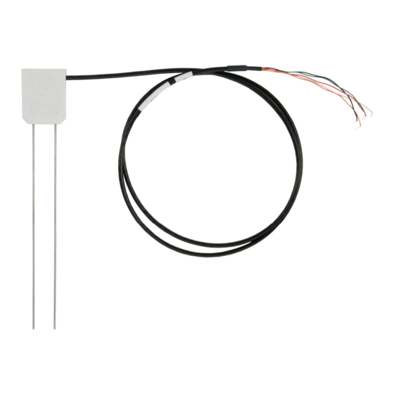
They output an SDI-12 signal that many Campbell Scientific data loggers can measure. The CS650 has 30 cm length rods, whereas the CS655 has 12 cm length rods. This manual uses CS650 to reference model numbers CS650 and CS655. Unless specifically stated otherwise, information in the manual applies equally to both models. -
Page 6: Quickstart
1. Open Short Cut and click Create New Program. 2. Double-click the data logger model. 3. In the Available Sensors and Devices box, type CS650. You can also locate the sensor in the Sensors > Meteorological > Soil Moisture > CS650/CS655 Water Content Reflectometer folder. - Page 7 4. Repeat step three for other sensors you want to measure. 5. In Output Setup, type the scan rate. If you chose to measure the CS650 hourly rather than every scan, this scan interval must be evenly divisible into an hour. Type a meaningful table name and type the Data Output Storage Interval.
-
Page 8: Overview
LoggerNet, RTDAQ, or PC400 to make sure it is making reasonable measurements. 5. Overview The CS650 measures volumetric water content, electrical conductivity, dielectric permittivity, and temperature of soils or other porous media. These values are reported through SDI-12 communications. - Page 9 Volumetric water content (VWC) is derived from the sensor sensitivity to the dielectric permittivity of the medium surrounding the sensor stainless-steel rods. The CS650 is configured as a water content reflectometer, with the two parallel rods forming an open-ended transmission line.
-
Page 10: Specifications
The CS650 handles this problem by making an electrical conductivity measurement then correcting the oscillator period accordingly. On-board processing within the sensor head calculates electrical conductivity from the signal attenuation measurement and combines the result with the oscillation period measurement to calculate the dielectric permittivity of the media and finally applies the Topp equation (Topp et al. -
Page 11: Electrical Specifications
U terminal Electromagnetic compatibility: View EU Declaration of Conformity documentation at www.campbellsci.com/cs650 External RF sources can affect CS650 measurements. CS650 circuitry should be located away from radio transmitter aerials and cables, or measurements discarded during RF transmissions. -
Page 12: Operational Specifications
FIGURE 6-1. CS650 and CS655 average current drain FIGURE 6-1 (p. 8) shows average current drain for different measurement rates and quantities of CS650 sensors. If the time between measurements is five minutes or longer, average current drain is approximately 0.15 milliamps per sensor. 6.2 Operational specifications Table 6-2 (p. - Page 13 1 to 81 and solution electrical conductivities ranging from 0 to 3 dS/m. ‡Precision describes the repeatability of a measurement. It is determined for the CS650 by taking repeated measurements in the same material. The precision of the CS650 is better than 0.05 % volumetric water content and 0.01 dS/m electrical conductivity.
-
Page 14: Installation
The CS650 measures the bulk dielectric permittivity, average volumetric water content, and bulk EC along the length of the rods, which is 30 cm for the CS650 and 12 cm for the CS655. The sensor rods can insert vertically into the soil surface or buried at any orientation to the surface. -
Page 15: Data Logger Wiring
SDI-12 programming. Table 7-1 (p. 11) shows the SDI-12 wiring for the CS650 water content reflectometer. SDI-12 data is transmitted to a CRBasic data logger odd numbered control or U terminal. Wiring information for RS-232 communications is provided in RS-232 wiring (p. -
Page 16: Programming
For the CR6 and CR1000X data loggers, triggering conflicts may occur when a companion terminal is used for a triggering instruction such as TimerInput(), PulseCount(), or WaitDigTrig(). For example, if the CS650 is connected to C3 on a CR1000X, C4 cannot be used in the TimerInput(), PulseCount(), or WaitDigTrig() instructions. -
Page 17: Operation
8. Operation 8.1 A200 and Device Configuration Utility The A200 Sensor-to-Computer Interface allows communications between a CS650 and a computer to change sensor settings through Device Configuration Utility software. 8.1.1 Using the A200 8.1.1.1 Driver installation If the A200 has not been previously plugged into your computer and your computer operating system is not Windows 7, the A200 driver needs to be installed. -
Page 18: Powering The Sensor
(p. 14). Connect the computer to the A200 USB port with the supplied USB cable. Launch Device Configuration Utility and search for CS650 Series from the Device Type list on the left. Select 9600 from the Baud Rate list. CS650 and CS655 Water Content Reflectometers... -
Page 19: Settings Editor Tab
Select Ok then Connect to begin communications with the CS650. 8.1.2.1 Settings Editor tab The Settings Editor tab shows settings stored in the CS650 operating system. Settings that may be modified include User Name, SDI-12 Address, and RS-232 Baud Rate. Attempts to change any of the other settings results in a “Commit failed. - Page 20 Default communications settings are 9600 baud, no parity, 1 stop bit, 8 data bits, and no error checking. After any changes to CS650 settings, select Apply to write the changes to the CS650 operating system. A configuration summary is then shown. The summary may be printed or saved electronically for future reference.
- Page 21 CS650 and CS655 Water Content Reflectometers...
-
Page 22: Send Os Tab
PA (μS) Period average Voltage ratio 8.1.2.2 Send OS tab The Send OS tab is used to update the operating system in the CS650. The operating system is available at www.campbellsci.com/downloads . The file to send has a filename extension of .a43, such as CS65X.Std.02.a43. -
Page 23: Sdi-12 Measurements
8.2 SDI-12 measurements The CS650 responds to SDI-12 commands M!, M1!, M2!, M3!, M4!, ?!, and I!. Table 8-3 (p. 19) shows the values returned for each of these commands. SDI12Recorder() Establish SDI-12 communications using the CRBasic instruction. See Data logger wiring (p. -
Page 24: M3! And M4! Commands
CS650 sensors can connect to the same data logger control or U terminal. Each must have a unique SDI-12 address. Valid addresses are 0 through 9, A through Z, and a through z. The CS650 ships with a default SDI-12 address of 0 unless otherwise specified at the time of ordering. - Page 25 The Topp et al (1980) equation used by the CS650 to estimate volumetric water content works well for most mineral soils up to a maximum water content of about 0.45. If the CS650 estimates the soil permittivity to be more than 42, which calculates to a volumetric water content of 0.52, then the M3! command reports 9999999 or NAN for volumetric water content.
-
Page 26: Use Of Multiplexers
8.2.2 Use of multiplexers Multiplexers such as Campbell Scientific AM16/32B can connect up to 32 CS650 sensors to a single control or U terminal. When using multiplexers, the simplest configuration is for all sensors to have the same SDI-12 address. -
Page 27: Topp Equation
+ 4.3•10 Research has shown that this equation works well in most mineral soils, so a soil specific calibration of the CS650 sensor is usually not necessary. For a soil specific calibration, you can generate an equation relating K to θ... -
Page 28: Temperature Correction Of Soil Electrical Conductivity
EC is outside the operational range of the sensor. 8.3.3.2 Temperature correction of soil electrical conductivity The EC value reported by the CS650 is bulk electrical conductivity. This value is temperature dependent, changing by 2% per degree Celsius. To compensate for the effect of temperature, convert EC readings to a standard temperature, such as 25 °C using the following equation:... -
Page 29: Insertion Error
8.3.5 Temperature dependence and correction The two temperature dependent sources of error in CS650 water content measurements are the effect of temperature on the operation of the sensor electronics and the effect of temperature on the dielectric permittivity of the soil. -
Page 30: Accurate Soil Temperature Measurement
1.55 g cm may require a media-specific calibration equation. In these cases, the user may develop a calibration equation to convert CS650 permittivity to volumetric water content over the range of water contents the sensor is expected to measure. 8.4.2 User-derived calibration equation A quadratic equation or third order polynomial can describe the relationship between soil permittivity and volumetric water content. -
Page 31: Collecting Laboratory Data For Calibration
8.4.3 Collecting laboratory data for calibration Water content reflectometer data needed for CS650 calibration are the CS650 permittivity reading and an independently determined volumetric water content. From this data, a linear or polynomial function can describe the sensor response to changing water content. For more... - Page 32 Repeat steps b through d for each of the remaining soil layers. 3. Carefully insert CS650 rods through the soil surface until the rods are completely surrounded by soil. Avoid moving the rods from side to side because this can form air voids around the rods.
-
Page 33: Collecting Field Data For Calibration
The volumetric water content is the product of the gravimetric water content and the bulk density The average water content for the replicates and the recorded CS650 permittivity are one datum pair to be used for the calibration curve fit. - Page 34 The following is the procedure for obtaining samples. 1. Use a shovel to form a vertical face of soil. 2. If using the CS650 within about 0.5 meters of the surface, insert the sensor into the face. 3. Add water to the surface using percolation.
- Page 35 The volumetric water content is the product of the gravimetric water content and the bulk density The average water content for the replicates and the recorded CS650 period are one datum pair to be used for the calibration curve fit.
-
Page 36: Calculations
Calculate gravimetric water content, θ , using To obtain soil bulk density, use Volumetric water content is calculated using 9. Maintenance and troubleshooting The CS650 does not require periodic maintenance. Table 9-1 (p. 33) provides troubleshooting information. CS650 and CS655 Water Content Reflectometers... - Page 37 Table 9-1: Symptom, cause, and solutions Symptom Possible cause Solution All CS650 output values read 0 No SDI12Recorder instruction Add SDI12Recorder instruction in data logger program to data logger program Conditional statement that Check logic of conditional triggers reading is not...
-
Page 38: References
New formulations and calibrations. Soil Sci. Soc. Am. J., 53:433-439. Topp, G.C., J.L. Davis & A.P. Annan. 1980. “Electromagnetic determination of soil water content: measurements in coaxial transmission lines,” Water Resources Research, v. 16, No. 3:574-582. CS650 and CS655 Water Content Reflectometers... -
Page 39: Appendix A. Importing Short Cut Code Into Crbasic Editor
Block. This adds an apostrophe (') to the beginning of each of the highlighted lines, which instructs the data logger compiler to ignore those lines when compiling. The Comment Block feature is demonstrated at about 5:10 in the CRBasic | Features video CS650 and CS655 Water Content Reflectometers... -
Page 40: Appendix B. Example Programs
This CRBasic example program measures one CS650 sensor on a CR1000X every 15 minutes, storing hourly averages of volumetric water content, electrical conductivity, and soil temperature and samples of permittivity, period average and voltage ratio. The CS650 has an SDI-12 address of 0. Wiring for the example is shown in Table B-1 (p. -
Page 41: Cr1000X With Two Cs650 Sensors On Same Control Port
The first CS650 has an SDI-12 address of 0 and the second has an address of 1. Wiring for the example is shown in Table B-2 37). -
Page 42: Cr1000X With 12 Cs650 Sensors On Multiplexer
B.3 CR1000X with 12 CS650 sensors on multiplexer This CRBasic example program measures 12 CS650 sensors on a AM16/32B multiplexer every 15 minutes, storing hourly averages of volumetric water content, electrical conductivity, soil temperature, permittivity, period average, and voltage ratio. All sensors are addressed with SDI- 12 address of 0. - Page 43 CRBasic Example 3: CR1000X with 12 CS650 sensors on multiplexer LCount Public CS650(12,6) DataTable (DatoutCS650,1,-1) DataInterval (0,60,Min,2) Average (72,CS650(),IEEE4,False) EndTable BeginProg Scan (15,Min,0,0) PortSet(C2,1) 'Turn AM16/32 Multiplexer On Delay(0,150,mSec) LCount=1 SubScan(0,uSec,12) PulsePort(C3,10000) 'Switch to next AM16/32 terminal SW12 (SW12_1,1) 'Apply power to CS650 Delay (0,3,Sec) 'Wait three seconds for sensor to warm up...
-
Page 44: Appendix C. Discussion Of Soil Water Content
Another useful property, soil porosity (ε), is related to soil bulk density as shown by the following expression. –3 The term ρ is the density of the soil solid fraction and is approximately 2.65 g cm solid CS650 and CS655 Water Content Reflectometers... -
Page 45: Appendix D. Sdi-12 Sensor Support
SDI-12, Serial Data Interface at 1200 baud, is a protocol developed to simplify sensor and data logger compatibility. Only three wires are necessary — serial data, ground, and 12 V. With unique addresses, multiple SDI-12 sensors can connect to a single SDI-12 terminal on a Campbell Scientific data logger. -
Page 46: Acknowledge Active Command (A!)
Table D-1: Campbell Scientific sensor SDI-12 command and response set Response Name Command Address Query a<CR><LF> aAb! Change Address b<CR><LF> Start Measurement atttn<CR><LF> aM1!...aM9! a<values><CR><LF> or aD0!...aD9! Send Data a<values><CRC><CR><LF> Information on each of these commands is given in the following sections. -
Page 47: Start Verification Command (Av!)
D commands. n = the number of values returned when one or more subsequent D commands are issued. For the aM! command, n is an integer from 0 to 9. CS650 and CS655 Water Content Reflectometers... -
Page 48: Stopping A Measurement Command
75 characters of data in response to a D command that follows a C! or CC! command. Data values are separated by plus or minus signs. Command: aD0! (aD1! … aD9!) CS650 and CS655 Water Content Reflectometers... -
Page 49: Sdi-12 Transparent Mode
Transparent mode is entered while the computer is communicating with the data logger through a terminal emulator program. It is accessed through Campbell Scientific data logger support software or other terminal emulator programs. Data logger keyboards and displays cannot be used. - Page 50 8. Type SDI12 and press Enter. 9. At the Select SDI12 Port prompt, type the number corresponding to the control port where the sensor is connected and press Enter. In this example the sensor is connected to C3. The CS650 and CS655 Water Content Reflectometers...
- Page 51 CR1000X. D.3 References SDI-12 Support Group. SDI-12: A Serial-Digital Interface Standard for Microprocessor-Based Sensors – Version 1.4. River Heights, UT: SDI-12 Support Group, 2017. https://sdi- 12.org/specification CS650 and CS655 Water Content Reflectometers...
- Page 52 See Product Details on the Ordering Information pages at www.campbellsci.com . Other manufacturer's products, that are resold by Campbell Scientific, are warranted only to the limits extended by the original manufacturer. Refer to www.campbellsci.com/terms#warranty for more information.
- Page 53 To obtain a Returned Materials Authorization or Repair Reference number, contact your CAMPBELL SCIENTIFIC regional office. Please write the issued number clearly on the outside of the shipping container and ship as directed. For all returns, the customer must provide a “Statement of Product Cleanliness and Decontamination”...
- Page 54 Do not recharge, disassemble, heat above 100 °C (212 °F), solder directly to the cell, incinerate, or expose contents to water. Dispose of spent batteries properly. WHILE EVERY ATTEMPT IS MADE TO EMBODY THE HIGHEST DEGREE OF SAFETY IN ALL CAMPBELL SCIENTIFIC PRODUCTS, THE CUSTOMER ASSUMES ALL RISK FROM ANY INJURY RESULTING FROM IMPROPER INSTALLATION, USE, OR MAINTENANCE OF TRIPODS, TOWERS, OR...
- Page 55 Campbell Scientific Regional Offices Australia France Thailand Location: Garbutt, QLD Australia Location: Vincennes, France Location: Bangkok, Thailand Phone: 61.7.4401.7700 Phone: 0033.0.1.56.45.15.20 Phone: 66.2.719.3399 Email: info@campbellsci.com.au Email: info@campbellsci.fr Email: info@campbellsci.asia Website: www.campbellsci.com.au Website: www.campbellsci.fr Website: www.campbellsci.asia Brazil Germany Location: São Paulo, SP Brazil...
Need help?
Do you have a question about the CS650 and is the answer not in the manual?
Questions and answers