
Related Manuals for Campbell CS110


Summary of Contents for Campbell CS110
- Page 1 CS110 Electric Field Meter Instruction Manual Issued: 29.5.12 © Copyright 2005-2012 Campbell Scientific Inc. Printed under Licence by Campbell Scientific Ltd. CSL 619...
- Page 3 CAMPBELL SCIENTIFIC, LTD. is not liable for special, indirect, incidental or consequential damages from the use, failure or malfunction of the CS110. In no event will CAMPBELL SCIENTIFIC, LTD. have liability in excess of the purchase price for the CS110.
- Page 5 PLEASE READ FIRST About this manual Please note that this manual was originally produced by Campbell Scientific Inc. primarily for the North American market. Some spellings, weights and measures may reflect this origin. Some useful conversion factors: Area: 1 in...
-
Page 7: Table Of Contents
3. CS110 Measurement Details ........6 4. Site Requirements and Recommendations ....8 4.1 Power Requirements ................. 8 4.2 Campbell Scientific, Inc. Power Supplies ..........9 4.3 Communication Options ................9 4.4 Site Recommendations ................10 5. Factory Calibration and Site Correction ....10 5.1 Factory Calibration ................. - Page 8 D.6 Motor O-ring Seal ................D-6 E. CS110 as a Slow Antenna ........E-1 E.1 Response of the CS110 Slow Antenna in the Frequency Domain ..E-1 E.2 Response of the CS110 Slow Antenna in the time Domain ....E-3 E.3 Programming ..................
- Page 9 10. CS110 Attached to Upward-Facing Flush-Mounted Plate for Site Correction ....................15 11. Site Correction Data for CS110 2 Metre CM10 Tripod Site ....16 12. Electric Field Measured with CS110 During Local Thunderstorm ..18 13. CS110 Stator, Shutter and Sense Electrode ..........32 14.
- Page 10 This is a blank page.
-
Page 11: General Description
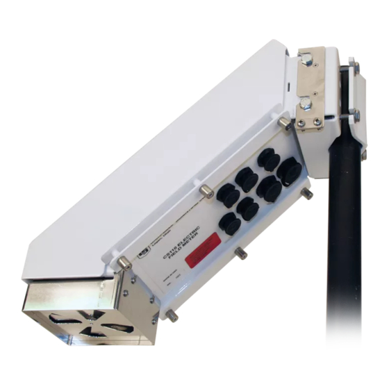
Reciprocating Shutter Figure 1. CS110 Electric Field Meter Unlike traditional rotating vane field mills, the CS110 uses a reciprocating shutter. A stepper motor opens and then closes the reciprocating shutter by 45° during measurements. The reciprocating shutter is electrically connected to ground potential by a flexible stainless-steel strap operated below its fatigue limit, resulting in an ultra-reliable electrical ground connection. -
Page 12: Cr1000 Datalogger
CS I/O cable (CS110CBL2). Examples of CS I/O peripherals include the CR1000 Keyboard Display and the COM220 phone modem. The DB9 end of CS110 RS-232 cable and CS110 CS I/O cable won’t fit through the conduit used on some enclosures, whereas the smaller circular end that connects to the CS110 will. -
Page 13: Digital I/O
Instruction Manual 1.5 Digital I/O Three general purpose 0 to 5 V digital I/O lines are available on the CS110 Power cable (CS110CBL3) that attaches to the circular power connector on the underside of the CS110. The blue, yellow, and green wires connect to control ports C1, C2, and C3 respectively. -
Page 14: Cs110 Specifications
Field enhancement due to typical inverted and elevated mounting requires additional site correction, estimated at ±5% accuracy when done in appropriate high field conditions. Practical outdoor CS110 electric field measurement accuracy is estimated at ±5% of reading + 8 V m for the CS110 2 metre CM10 Tripod Site. - Page 15 The self-checking also monitors internal humidity, insulator cleanliness, and power supply voltage, and verifies that CS110 components such as the charge amplifier and shutter open/close are functioning properly. Operating Temperature Range: -25° to 50°C standard, -40° to +85°C optional RH Range: 0 to 100% RH Dimensions: 15.2 x 15.2 x 43.2 cm (6"...
-
Page 16: Cs110 Measurement Details
CS110 Electric Field Meter Warranty: The CS110 has a one year warranty against defects in materials and workmanship. A three year warranty is provided for the embedded CR1000 Measurement and Control Module. 3. CS110 Measurement Details The charge amplifier circuitry of the reciprocating electric field meter is depicted in Figure 2. -
Page 17: Charge Amplifier Output During An Electric Field Measurement Cycle
Instruction Manual Figure 3. Charge Amplifier Output During an Electric Field Measurement Cycle Offset voltages V and V are zero field reference measurements made when the off1 off2 shutter is closed, and utilized to accurately estimate voltage ΔV when the shutter is completely open. -
Page 18: Site Requirements And Recommendations
The current required by the CS110 powered from 12 V DC is shown in Figure 4. As depicted in the figure, the average electric field meter current is a function of the desired measurement rate, which is user-controlled by means of the datalogger program, making economical remote solar power feasible. -
Page 19: Campbell Scientific, Inc. Power Supplies
Measurement Interval (Seconds) Figure 4. CS110 Average Current Consumption versus Measurement Interval The CS110 requires 11 V to 16 Vdc with a peak current demand of 750 mA during motor operation. The CS110 Power Cable (PN 010350) is used to connect the dc power supply to the CS110. -
Page 20: Site Recommendations
The large hexagonal parallel plate electric field calibrator illustrated in Figure 5 is used for factory calibration of the CS110 Electric Field Meter. The large physical size was incorporated to minimize non- ideal fringing effects. -
Page 21: Parallel-Plate Electric Field Meter Calibration Chamber
Figure 5 is ± 1 %. The electric field offset of the CS110 can be measured by covering the stator with a clean Zero Electric Field Cover (PN: 010346). If the resulting zero field reading... -
Page 22: Factory Calibration Data For Cs110 Sn: 1026
CS110 Electric Field Meter with the zero field cover exceeds an absolute value of 60 V/m then cleaning of electrodes in the CS110 is suggested. The factory calibration data for a typical CS110 factory calibration and resulting determination of M = 84.32... -
Page 23: Site Correction
5.2 Site Correction As previously mentioned, each CS110 is factory calibrated in a parallel plate calibration fixture resulting in calibration equation 4. However, when monitoring the Earth’s electric field, equation 4 is valid only if the instrument aperture is mounted flush with the Earth’s surface and upward-facing. -
Page 24: Cs110 2 Metre Cm10 Tripod Site
CS110 Electric Field Meter Figure 8. CS110 2 Metre CM10 Tripod Site. Inverting the CS110 reduces the effective gain while elevating it’s height above ground enhances the gain, with respect to an ideal upward-facing flush-mounted geometry. It should be mentioned that this gain enhancement reduces the effect of unwanted electrical field offsets. -
Page 25: Campbell Scientific, Ltd. Electric Field Meter Site Correction Facility
Instruction Manual Figure 9. Campbell Scientific, Ltd. Electric Field Meter Site Correction Facility An upward-facing calibration kit (PN: 01034) was developed to hold the CS110 in a flush-mounted upward-facing position, as illustrated in Figure 10. Figure 10. CS110 Attached to Upward-Facing Flush-Mounted Plate for Site Correction... -
Page 26: Site Correction Data For Cs110 2 Metre Cm10 Tripod Site
-4000 -6000 -8000 -10000 Uncorrected (Csite = 1) Electric Field (volt/meter) for 2 Meter Mounted CS110 on CM10 Uncorrected (C = 1) Electric Field (volt/meter) for 2 Meter Mounted CS110 on CM10 site Tripod. SN: 1023 (Mparallel_Plate = 81.77 volt/meter*millivolt) Tripod. -
Page 27: Lightning Warning
Instruction Manual The user is responsible for determining if a CS110 site is representative of the CS110 2 Metre CM10 Tripod Site, and if not, for determining the appropriate site correction. The atmospheric electric field at the Earth’s surface during fair weather conditions is on the order of –100 V/m;... -
Page 28: Electric Field Measured With Cs110 During Local Thunderstorm
The CS I/O port, along with the three general purpose 0 to 5 V digital I/O ports (C1 - blue, C2 - yellow and C3 - green) available on the CS110 Power cable (CS110CBL3) can be used for a serial digital interface. Control ports C1, C2 and C3 can also be used to conditionally control warning and alarm indicators. -
Page 29: Crbasic Programming
See Section 8 for details on individual instructions. Appendix F contains some example CRBasic programs for the CS110. A simple example CRBasic program illustrating some of the general concepts follows: 'Comments can be inserted in CRBasic utilizing a single quote ('). - Page 30 PanelTemp, VoltDiff, Battery, and CS110 are measurement instructions that return the temperature inside the CS110 case, relative humidity inside the CS110 case, the voltage being provided to the CS110 to power the instrument and the measured electric field, respectively. These and other measurement instructions are discussed more fully in Section 7 on CS110 Measurement Instructions.
- Page 31 = 0 'Initialize disable variable for Efield average in slow table. SW12 (1 ) 'Apply 12 V to warm-up Temp and RH probe at least 150 ms. CS110(E_field,leakage_cur,status,_60Hz,Mcorrected,0) VoltSe (RH,1,mV2500,1,1,0,250,0.1,0) VoltSe (air_temp,1,mV2500,2,1,0,250,.18,-40) SW12 (0) 'Turn off power to Temp and RH probe.
-
Page 32: Cs110 Measurement Instructions
If the shutter cannot properly close then the CS110 will return NAN for the electric field measurement along with a status value indicating that the motor could not properly close the shutter. - Page 33 The Battery instruction is used to measure the input voltage of the power supply to the CS110 and follows: Battery (Dest) The PanelTemp instruction is used to measure the temperature of a thermistor located within the CS110 case and follows:...
-
Page 34: Measuring Electric Field
5 Hz maximum rate of the CS110 electric field measurement instruction. In the slow antenna mode the CS110... -
Page 35: Measuring Solar Radiation Or Barometric Pressure
VoltDiff measurement. 8.4 Measuring Solar Radiation or Barometric Pressure Circular connector labelled SOLAR RADIATION on the CS110 can be used to connect up an LI200X solar radiation sensor. Alternately, a special cable, the CS110 BAROMETRIC PRESSURE SENSOR CABLE (17460), can be purchased and connected to the SOLAR RADIATION connector to interface to either the CS100 or the CS106 barometric pressure sensor. -
Page 36: Measuring Rainfall
The following three screen captures show the settings for each of the three links in the path from COM Port 1 on the PC to the CS110 with the factory default PakBus address of 1. Use LoggerNet Tool Bar’s “Setup” button or “EZ Setup” button to... - Page 37 Instruction Manual...
- Page 38 “Apply” button is greyed out once it has been executed. Once this is done, switch to the “Connect” button on the LoggerNet Tool Bar, select the CS110, and select “Connect”. If the connection is made and the stations time shows up in the window, you can then select the “Numeric:”...
- Page 39 Instruction Manual If you have changed the CR1000’s PakBus address and subsequently forgotten it, you can download from http://www.campbellsci.com/downloads at no cost, a software package named Device Configuration Utility that will discover the PakBus address. Run the software and set it up with device type set to CR1000, specify the correct COM port, and select “Connect”...
-
Page 40: Maintenance
10. Maintenance 10.1 Checking Site Ground Integrity The CS110 electric field meter needs to be electrically connected to Earth ground for valid measurements. It is recommended that the integrity of this Earth Ground connection be checked periodically by verifying that the resistance of the stator to Earth Ground rod is <1 Ω. - Page 41 Instruction Manual Loctite also makes a similar product and some information on their products may be found at http://content.loctite.com/sticks/silver-as.html. Following is an excerpt from their web site: Heavy-duty, temperature-resistant up to 1600°F, petroleum-based lubricant fortified with graphite and metallic flake. Features &...
-
Page 42: Self-Check Features
CS110 Electric Field Meter 10.3 Self-Check Features The CS110 has been designed to provide reliable electric field measurements and to simplify and minimize maintenance. Scheduled maintenance may not be required, as the CS110 incorporates extensive self-checking, and provides status information about each measurement. An example CS110 instruction follows. -
Page 43: Changing Desiccant
CS110. One brush (CSI PN #17578) ships with each CS110. Large offsets are likely due to electrical charges residing insulative deposits on metallic surfaces, while large leakage currents are likely due to contaminated insulators. -
Page 44: Inside Of Cs110 Case Illustrating Bracket For Holding Desiccant
1. Remove the CS110 case lid by unscrewing the captive screws that attach the lid to the main body of the CS110. 2. Inspect the gasket on the CS110 lid making sure that a good seal is possible when the lid is replaced. -
Page 45: Checking Shutter/Encoder Alignment
For the CR1000 datalogger a two year re-calibration interval is recommended, with longer intervals being sensible for users that find negligible instrument drift over a two year period. The embedded CR1000 datalogger inside the CS110 case should... -
Page 46: References
± 10%, a parallel plate factory calibration is recommended every three years. The expected lifetime of the CS110 is 5 to 10 years, again depending upon the operational environment. Instruments operated in coastal environments will likely suffer from external finish degradation and/or operational failure sooner than instruments operated in dry inland environments. - Page 47 ± 10%, a parallel plate factory calibration is recommended every three years. The expected lifetime of the CS110 is 5 to 10 years, again depending upon the operational environment. Instruments operated in coastal environments will likely suffer from external finish degradation and/or operational failure sooner than instruments operated in dry inland environments.
-
Page 49: Cs110 Measurement Status Codes
10 is given the highest priority, status 9 the second highest, and 8 the third highest priority of CS110 status codes. Next in priority are codes 16, 15, 14, 13, 12, and 11 followed by 7, 6, 5, 4, 3, 2 and 1. - Page 50 Appendix A. CS110 Measurement Status Codes Status codes 11 through 16: Measurement warnings and errors. status = 11, Leakage current exceeds compensation range of ± 4.2 nA. Return measured Efield value. status = 12 Failed charge-amplifier self check. Return NAN instead of measured Efield value.
-
Page 51: Cs110 Accessories
The CR1000 keyboard display (CR1000KD) is a convenient CR1000 user interface that can be directly connected to the CS110. The CR1000 keyboard display connects to the CS110 through the CS I/O port, requiring a CS110 CS I/O Cable (CS110CBL2-L). The CR1000KD can be used to view data and programs, and to make simple program modifications. - Page 52 Appendix B. CS110 Accessories This is a blank page.
- Page 53 The following information describes the connectors that mate with the built- in (bulkhead) connectors on the CS110. Connector pin numbering for the 6 and 9 pin connectors are shown below. The view is a view of the solder-cup side of the cabled connector. The circular connectors are Mini-Con-X type from Conxall.
-
Page 54: Cs110 Connector Pin-Outs
Appendix C. CS110 Connector Pin-outs RAIN CONNECTOR Connector is male and is CSI PN 9889 (Conxall #6282-6PG-522 or Switchcraft #EN3C6M). Pin 1 is indicated w/ a dot Description empty empty Pulse channel 2 empty Power ground Power ground CSIO CONNECTOR... - Page 55 Appendix C. CS110 Connector Pin-outs SOLAR RADIATION CONNECTOR Connector is male and is CSI PN 9889 (Conxall #6282-6PG-522 or Switchcraft #EN3C6M). Pin 1 is indicated w/ a dot Description Single-ended channel 5 or high side of differential channel Single-ended channel 6 or low side of differential channel...
- Page 56 Appendix C. CS110 Connector Pin-outs This is a blank page.
-
Page 57: Servicing The Cs110
(PN: #17533) in order to form a good seal. D.2 Changing Out the CR1000 The CR1000 datalogger is accessible in the CS110 by removing the case lid. The CR1000 is secured to the CS110 via the desiccant holder bracket along with the two thumb screws on the CR1000 module. -
Page 58: Changing Out Motor Assembly
CS110 electrodes and change desiccant in the sealed CS110 case. D.5 Shutter/Encoder Alignment A factory trim is done to align the position of the CS110 shutter with an Index mark on the rotary position encoder. Re-trimming of the shutter/encoder alignment becomes necessary after encoder disassembly. - Page 59 Appendix D. Servicing the CS110 'CS110 program to trim index to fully closed shutter position (CS110_Index_Trim.cr1). ' Index/shutter trim procedure follows: ' 1. Take at least 8 full-steps open via flag(1) in order to synchronize ' motor coils with motor controller phase state.
- Page 60 Once in the fully closed position, hook an oscilloscope or dc voltmeter to the Index test pin on the CS110 panel PCB. The Ports and Flags button on the LoggerNet connect screen along with a graphical display can also be used for trimming if the update interval is set to 50 ms.
- Page 61 The CS110Shutter instruction can be used to open, pause and then close the CS110 shutter to allow visual inspection/verification of proper opened and closed shutter positions. The following CS110 program can be used to verify proper opening and closing of the shutter. Stator to shutter overlap exists in the fully opened and fully closed positions so that slight shutter position variations do not alter the exposed area to the sense electrode.
-
Page 62: Motor O-Ring Seal
A double-seal O-ring is located on the motor shaft underneath the CS110 shutter to help seal the CS110 case. Use Allen head screwdriver to remove the 1 screw and loosen the second (primary) set screw in the shutter hub, in order to access and replace the motor O-ring. -
Page 63: Cs110 As A Slow Antenna
0.708 true The CS110 can measure the slow antenna output at rates up to 50 Hz (100 Hz may be possible but it has not been tested), using the fast integration (250 μs integration) for the VoltDiff instruction. Voltage measurements using the 250 μs integration duration for the analogue integrator, result in an upper 3 dB bandwidth of 1.8 kHz (0.555 ms). -
Page 64: Cs110 Slow Antenna Frequency Response
Appendix E. CS110 as a Slow Antenna Overall Frequency Response of CS110 Slow-Antenna Measurement with 250 us Integration 0.999 0.833 0.667 MagSys f ( ) 0.333 0.167 × × 1 10 1 10 10000 Frequency (Hz) Figure E-1. CS110 slow antenna frequency response. -
Page 65: Response Of The Cs110 Slow Antenna In The Time Domain
The following graphs shows one lightning strike measured at 50 Hz by both the CS110 slow antenna and by one of Kennedy Space Centre’s (KSC) field mills. In Figure E-3 the KSC electric field meter readings have been converted to efield change per measurement. -
Page 66: Ksc Electric Field Change And Cs110 Slow Antenna Data
Since that time, the CS110 has been improved and now has the ability to sync to within ±10 µs of the GPS signal’s PPS pulse. The resolution of accuracy for the clock set is 10 microseconds if the internal CR1000 datalogger has a hardware revision number greater than 007 (RevBoard field in the datalogger's Status table). -
Page 67: Programming
Sequential Mode command and the Pipeline Mode command used in the above example to exist in the same program. For the CS110 to be able to switch between measuring the electric field with the CS110 instruction and the electric field change in the “slow antenna”... -
Page 68: Calibration
The factory calibration described in Section 5 applies to the maximum amplitude of the step response of the CS110 when it is operating as a slow antenna. Switching in the 200 MΩ resistor in the feedback path simply slows the decay of... - Page 69 Appendix F. Example CRBasic Programs An example CS110 weather station program using a variable electric field measurement rate in order to minimize current consumption in solar powered applications follows. 'CS110 efield and weather station program with variable measurement 'rate for low-power consumption.(CS110_low_power.cr1).
- Page 70 = 0 'reset the count for SLOW_INTERVAL meas_error = 0 'Initialize disable variable for Efield average in slow table. CS110(E_field,leakage_cur,status,_60Hz,Mcorrected,0) If E_field = NAN Then meas_error = 1 'Disable output to slow table if efield = NAN. E_field_int = FAST_INTERVAL...
-
Page 71: Example Crbasic Programs
Appendix F. Example CRBasic Programs EndIf E_status(status) = 1 'Set appropriate element in status array. Endif If E_field <> NAN Then AvgRun (run_avg10,1,E_field,10) 'Used for average output in fast table. AvgRun (abs_run_avg600,1,ABS(E_field),600) 'Used to stay longer at fast interval. EndIf if (E_field>100 or ABS(E_field)>=300 or abs_run_avg600>=300)and (battery_volt>11.0) then E_field_int = FAST_INTERVAL else... - Page 72 Appendix F. Example CRBasic Programs This is a blank page.
-
Page 73: Cs110 2 Metre Cm10 Tripod Site
Site FIGURE G-1. CS110 2 Metre CM10 Tripod Site The Tripod_CS110 site consists of the CS110 mounted on the CM10 Tripod at a height of 2 metres, and an ENC 12/14 enclosure. The following may affect the site calibration factor, C site •... - Page 74 Attach the cap to the top of the mast. Attach the CS110 mounting bracket to the mast with the top of the bracket about 23.5 cm (9¼ inches) below the top of the cap on the mast but don’t tighten bolts very tight as it will likely need to be rotated and either raised or lowered slightly.
- Page 75 Tilt the solar panel at an angle less than horizontal that is equal to the latitude plus 10 degrees (see solar panel manual). Ground the CS110 Electric Field Meter (Figure G-2), the tripod, and the battery (through the enclosure ground) with three separate ground wires as shown in Figure G-3.
- Page 76 = 81.77 parallel_plate Each CS110 recorded one minute averages of 1 second measurements of electric field data for the same 2200 to 2300 hour time period on October 2, 2005. The data from both units is plotted in Figure G-4. A best-fit line was computed. The linear regression yields a C = 0.105 for the Tripod CS110 Only Site.
- Page 77 Tripod CS110 Only Uncorrected E_Field 1_Min_Avg volts/m -8000 Linear (Tripod CS110 Only Uncorrected E_Field 1_Min_Avg volts/m) -10000 Uncorrected (Csite = 1) Electric Field (volt/meter) for Tripod CS110 Only site SN: 1023 Mparallel_Plate = 81.77 volt/meter*millivolt FIGURE G-4. Determination of C site...
- Page 78 Appendix G. CS110 2 Metre CM10 Tripod Site This is a blank page.
-
Page 79: Tripod Cs110 And Strikeguard Site
Appendix H. Tripod CS110 and StrikeGuard Site H.1 Tripod CS110 and StrikeGuard FIGURE H-1. Tripod CS110 and StrikeGuard The Tripod CS110 and StrikeGuard Site includes the following that affect C site • CM10 Tripod • StrikeGuard Lightning Detector • CS110 Electric Field Meter •... -
Page 80: Installation Of The Tripod Cs110 And Strikeguard Site
Attach the cap to the top end of the mast. Attach the CS110 mounting bracket to the mast with the top of the bracket about 23.5 cm (9¼ inches) below the top of the cap on the mast but don’t tighten bolts very tight as it will likely need to be rotated and either raised or lowered slightly. - Page 81 Tilt the solar panel at an angle less than horizontal that is equal to the latitude plus 10 degrees (see solar panel manual). Ground the CS110 Electric Field Meter (Figure H-3), the tripod, and the battery (through the enclosure ground) with three separate ground wires as shown in Figure H-4.
- Page 82 Appendix H. Tripod CS110 and StrikeGuard Site FIGURE H-4. Grounding the Tripod and Battery Stake the tripod to the ground or weight it down with sand bags. Connect power and communication cables as shown in Figure H-5.
- Page 83 Appendix H. Tripod CS110 and StrikeGuard Site FIGURE H-5. Connections for Combined System Power and communication cables should be run down the equator side of the mast and under the enclosure as shown. Wire-tie all cables into place so they don’t...
- Page 84 = 81.77. parallel_plate Each CS110 recorded one minute averages of 1 second measurements of electric field data for the same one hour time period from 3 AM to 4 AM on August 11, 2005. The data from both units is plotted in Figure H-6. A best-fit line was computed. The linear regression yields a C = 0.108 for the Tripod CS110 and StrikeGuard Site.
- Page 86 CAMPBELL SCIENTIFIC COMPANIES Campbell Scientific, Inc. (CSI) 815 West 1800 North Logan, Utah 84321 UNITED STATES • www.campbellsci.com info@campbellsci.com Campbell Scientific Africa Pty. Ltd. (CSAf) PO Box 2450 Somerset West 7129 SOUTH AFRICA • www.csafrica.co.za sales@csafrica.co.za Campbell Scientific Australia Pty. Ltd. (CSA)
Need help?
Do you have a question about the CS110 and is the answer not in the manual?
Questions and answers