Table of Contents
Advertisement
Certified for Compliance to the Following Standards:
• ASSE 1017 – Performance Requirements for
Temperature Actuated Mixing Valves for Hot Water
• CSA B125.3 – Plumbing Fittings
• ANSI/NSF/CAN 372 – Drinking Water System
Components (Lead content)
Read the instructions in this manual before beginning installation. Save these instructions and
refer to them for inspection, maintenance, and troubleshooting information.
For questions regarding the operation, installation or maintenance of this product, visit bradleycorp.com or call 800.BRADLEY (800.272.3539).
Product warranties and parts information may also be found under "Resources" on our website at bradleycorp.com.
215-1927 Rev. C: ECO 23-09-005
© 2023 Bradley
Page 1 of 37
11/20/2023
Installation
S59-5000 Series
Navigator
Valves (DMV)
S59-5075 ¾" NPT Valve
S59-5100 1" NPT Valve
S59-5125 1¼" NPT Valve
S59-5150 1½" NPT Valve
S59-5200 2" NPT Valve
Scan or click code to view
Installation Guide (English)
Digital Mixing
®
Scan or click code to view
Installation Guide (French)
P.O. Box 309
Menomonee Falls, WI 53052 USA
800 BRADLEY (800 272 3539)
+1 262 251 6000
bradleycorp.com
Scan or click code to view
Installation Guide (Spanish)
Advertisement
Table of Contents

Related Manuals for Bradley S59-5000 Series


Summary of Contents for Bradley S59-5000 Series
- Page 1 For questions regarding the operation, installation or maintenance of this product, visit bradleycorp.com or call 800.BRADLEY (800.272.3539). Product warranties and parts information may also be found under “Resources” on our website at bradleycorp.com.
-
Page 2: Table Of Contents
Appendix F: Alarms Types & LED/LCD Displays ......37 The Navigator S59-5000 Series Digital Mixing Valve is intended to be but one component in an overall risk management plan as described ® by ANSI/ASHRAE Standard 188, "Legionellosis: Risk Management for Building Water Systems". When installed and used as designed and intended, the Navigator digital mixing valve can help reduce bacteria in domestic hot water recirculation systems. -
Page 3: Safety Information
• 120 VAC power for 24 VAC transformer • Electrician tools to make wire connections • Cold water supply inside the controller • Hot water supply • Fasteners for drywall or cement wall installation Bradley • 215-1927 Rev. C: ECO 23-09-005 11/20/2023... -
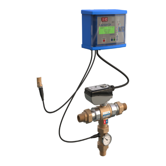
Page 4: Components
Plug In Actuator Sensor Cable/Clamp for Return Line Valve Body Check Valve Assembly with Fiber Washer Fiber Washer Tailpiece Outlet Temperature Sensor Cable Fiber Washer Gauge Adaptor Tailpiece Nut Temperature Gauge Fiber Washer Bradley • 215-1927 Rev. C: ECO 23-09-005 11/20/2023... -
Page 5: Product Performance & Specifications
Resistance: 10,000 Ohms @ 77°F (25°C) Time Constant: 2.5 Max. Distance for Mixed Outlet or Return (recirculation) Sensor: 500 ft (150 m) cable 2 conductor x AWG 18 800 ft (250 m) cable 2 conductor x AWG 16 Bradley • 215-1927 Rev. C: ECO 23-09-005 11/20/2023... -
Page 6: Mounting Dimensions
6" 7" 4" 26.4 S59-5200 (358.8) (374.7) (247.7) (88.9) (152.4) (177.8) (101.6) (11.97) ¹ Includes controller weight—2.7 lb (1.22 kg) and actuator weight—1.5 lb (0.68 kg) A NPT A NPT A NPT Bradley • 215-1927 Rev. C: ECO 23-09-005 11/20/2023... -
Page 7: Plumbing Installation
Refer to “Components” on page 4 for check valve assembly. Install the mixing valve with the outlet facing downward or facing to the side. DO NOT install mixing valve with outlet upward! Bradley • 215-1927 Rev. C: ECO 23-09-005 11/20/2023... -
Page 8: Optional Water Recirculation Setup
The positive shutoff design of the valve mitigates the issue of temperature creep where the system will eventually reach the temperature within the storage tank (non-digital valves also employ the use of an aquastat to control this occurrence) Bradley • 215-1927 Rev. C: ECO 23-09-005 11/20/2023... -
Page 9: Electrical Wiring
3 x AWG 18 8.25 / 210 2 x AWG 16 6.25 / 160 2 x AWG 16 6.25 / 160 2 x AWG 16 7 / 180 2 x AWG 16 6.25 / 160 Bradley • 215-1927 Rev. C: ECO 23-09-005 11/20/2023... - Page 10 8. Relay 4 9. Relay 2 Refer to “Relay Functions & Wiring” on page 25 for the functions for each relay. CAUTION Connections must NOT create pull stresses on the circuit board. Bradley • 215-1927 Rev. C: ECO 23-09-005 11/20/2023...
- Page 11 RELAY 1 – Recirc Pump (Disinfection) RELAY 2 – Alarm (Unsuccessful Disinfection Cycle) Cold RELAY 3 – Second Thermostat (Aquastat) RELAY 4 – Flushing Valve (Reduce Temperature) Return Line Temperature Mixed Outlet Sensor Temperature Sensor Bradley • 215-1927 Rev. C: ECO 23-09-005 11/20/2023...
- Page 12 Two wires inside "Mixed Outlet" sensor cable are connected to terminal 19 and 20. Two wires inside "Return" sensor cable are connected to terminal 21 and 20. The two wires in each sensor cable can be reversed as polarity is not relevant. Bradley • 215-1927 Rev. C: ECO 23-09-005 11/20/2023...
- Page 13 TUESDAY 01/01/2022 Tm127°F Tr120°F – ADJUSTMENT RUNNING Battery Charging Carefully reinstall the electrical wiring base into the housing. Replace the front cover onto the display and tighten the screw to secure. Bradley • 215-1927 Rev. C: ECO 23-09-005 11/20/2023...
-
Page 14: Unit Setup & Test
Live Rela RS485 Rela Mixed Outlet (Brown) – Common Rela (Blue or Black) Return (Brown) Thermal Shock Rela Activation Shock Shock Battery Enabled Disabled Battery Connection (factory setting) Battery Connected Battery Disconnected Bradley • 215-1927 Rev. C: ECO 23-09-005 11/20/2023... - Page 15 “Tr” is the measured return water temperature from the temperature sensor installed at the return line. If setting up a disinfection program is not required and the plumbing is properly connected and watertight, the system is ready to run. Bradley • 215-1927 Rev. C: ECO 23-09-005 11/20/2023...
- Page 16 This device must be checked for final temperature and adjusted as necessary. DO NOT SKIP THIS STEP!!! Test the system weekly by checking the hot water temperature at end user fixtures. Bradley • 215-1927 Rev. C: ECO 23-09-005 11/20/2023...
-
Page 17: Operation Modes
The Adjustment mode is the default DMV operating status. The DMV TUESDAY 01/01/2022 measures mixing water temperature at the valve outlet and adjusts Tm127°F Tr120°F the mixing valve position to maintain the desired set temperature ADJUSTMENT programmed as SET1. RUNNING Bradley • 215-1927 Rev. C: ECO 23-09-005 11/20/2023... -
Page 18: Disinfection Mode
(default is no days) and the Time ON and Time OFF parameters are filled in Prog. day 1234567 (default is 02:00 for Time On, 03:00 for Time Off). Time ON 02:00 Time OFF 03:00 Bradley • 215-1927 Rev. C: ECO 23-09-005 11/20/2023... - Page 19 The return water temperature is not used. If the temperature displays on the LCD screen, it is used for monitoring purposes only. Default SET_MAX is 149°F. It can be adjusted from 122–194°F (50–90°C). Bradley • 215-1927 Rev. C: ECO 23-09-005 11/20/2023...
- Page 20 The return water temperature is not used. If the temperature displays on the LCD screen, it is used for monitoring purposes only. Bradley • 215-1927 Rev. C: ECO 23-09-005 11/20/2023...
- Page 21 The alarm is recorded in a log. The unsuccessful disinfection alarm can be cleared after a button on the controller is pressed and a successful disinfection is conducted. Bradley • 215-1927 Rev. C: ECO 23-09-005 11/20/2023...
- Page 22 If the disinfection temperature is not successful, the alarm for an unsuccessful disinfection alarm is generated. The alarm is recorded in a log. The unsuccessful disinfection alarm can be cleared after a button on the controller is pressed and a successful disinfection is conducted. Bradley • 215-1927 Rev. C: ECO 23-09-005 11/20/2023...
-
Page 23: Flushing Mode
Relay 4 controls the valve. tFLUX 0060” Set tFLUX to the desired flushing duration (in seconds). Relay 1, Relay 4, and the controller return to the Adjustment mode after the flushing process is complete. Bradley • 215-1927 Rev. C: ECO 23-09-005 11/20/2023... -
Page 24: Thermal Shock Mode
Thermal Shock mode is complete. If needed, the Thermal Shock mode can be stopped by pressing the DISINFECT button and then confirming with the ENTER button, or by using the remote control. Bradley • 215-1927 Rev. C: ECO 23-09-005 11/20/2023... -
Page 25: Anti-Clog Function
Activates alarm for sensor fault, battery fault, blackout, or clock failure. Second thermostat for thermal disinfection, wired in parallel to High Temperature thermostat. Used to increase hot water supply temperature for thermal disinfection. Flushes valve. Bradley • 215-1927 Rev. C: ECO 23-09-005 11/20/2023... -
Page 26: Relay Functions & Wiring
Wiring diagram of Relay 1 with a clock for Wiring diagram of Relay 3 for connecting the managing the recirculation pump times. second thermostat. Relay 1 Relay 3 140°F 160°F Recirculation Pump Storage Primary Pump Bradley • 215-1927 Rev. C: ECO 23-09-005 11/20/2023... -
Page 27: Alarm Management
Relay 2 (provided by others) provides a connection to an external alarm that can be installed at any desired location. When the Thermal Shock function is in process, the alarm signal turns on to warn people that disinfection is in process. Refer to Section 11 for the details regarding Relay 2. Bradley • 215-1927 Rev. C: ECO 23-09-005 11/20/2023... -
Page 28: Lock Keypad (Access Pin Code)
If the Access PIN Code is lost or misplaced, the Lock function can be overridden (the Access PIN code is forced to 0000) by pressing a button on the back of the panel for 5 seconds or by sending a command through the RS485 interface. Bradley • 215-1927 Rev. C: ECO 23-09-005 11/20/2023... -
Page 29: History Log
If a fault occurs in one or both sensors, the hourly average data will be represented on the display by dashes. If there are any gaps or unavailable data due to a change of date, time, etc., the related cells will contain dashes. Bradley • 215-1927 Rev. C: ECO 23-09-005 11/20/2023... -
Page 30: Remote Control
Refer to the Bradley website for a list of registers (points) for mapping the DMV information to Modbus. Configuration, mapping, hardware (routers, modem, etc.), and software are customer/ user responsibility. -
Page 31: Troubleshooting
Check if the anti-clog function is disabled by accident (refer to Section 10 on page 25). The internal components of the valve can be descaled by immersing in a suitable descaling fluid. Follow setup procedure again after maintainable components have been checked. Bradley • 215-1927 Rev. C: ECO 23-09-005 11/20/2023... -
Page 32: Appendix A: Battery Specifications
See the “Alarm Management” on page 27. In principle, a battery fault should not affect any of the controller functions, unless there is also a power supply failure. Bradley • 215-1927 Rev. C: ECO 23-09-005 11/20/2023... -
Page 33: Appendix B: Control Panel Configuration Buttons & Displays
Sensor Warning Display – "Short Circuit" progress, reset) HANGE (blinking) DATE/TIME bradleycorp.com 01/01/2022 MIXED C° RETURN C° DISINFECT MENU ENTER 00:00 INFECT MENU ENTER HANGE Bradley • 215-1927 Rev. C: ECO 23-09-005 11/20/2023 DATE/TIME bradleycorp.com 01/01/2022 00:00 INFECT MENU ENTER HANGE... -
Page 34: Appendix C: Controller Setting Parameters & Ranges
Duration of the flushing phase that will From 0–2550 sec in 000 sec start automatically when a disinfection 10 sec steps phase is completed. Bradley • 215-1927 Rev. C: ECO 23-09-005 11/20/2023... - Page 35 Countdown Countdown before activating thermal 0–999 min 0001 min shock Activate countdown Enables activation of countdown before NO = not active NONE thermal shock YES = active Bradley • 215-1927 Rev. C: ECO 23-09-005 11/20/2023...
-
Page 36: Appendix D: Disinfection Program Comparison
1–4320 minutes 005 minutes manually Countdown Countdown before activating Thermal Shock mode 0–999 minutes 0001 minute NO = Not Active Activate Countdown Enables countdown activation before Thermal Shock mode NONE YES = Active Bradley • 215-1927 Rev. C: ECO 23-09-005 11/20/2023... -
Page 37: Appendix F: Alarms Types & Led/Lcd Displays
AL7: YES (AL7): Stored in 0, 1A, 1B & 2 Status OK LED goes NONE screen (alternating Battery Damaged the day log Off (alarm LED does with the working not illuminate) screen) Bradley • 215-1927 Rev. C: ECO 23-09-005 11/20/2023...
Need help?
Do you have a question about the S59-5000 Series and is the answer not in the manual?
Questions and answers