Advertisement
Quick Links
Installation
Packing List
•
•
•
IS
T H
•
E
S ID
U P
215-1296 Rev. E EN 10-09-010
© 2012 Bradley
Page 1 of 5
10/1/2012
Read this entire installation manual to ensure proper installation.
When finished with the installation, file this manual with the owner or
maintenance department. Compliance and conformity to local codes and
ordinances is the responsibility of the installer.
Hot limit screw is set in the maximum temperature position. Failure to
adjust properly may result in serious scalding. This valve may not protect
from scalding if there is a failure of other temperature-controlling devices
elsewhere in the plumbing system. Excessive heat may cause damage to
internal parts.
Separate parts from packaging and make sure all parts are accounted for
before discarding packaging material. If any parts are missing, do not begin
installation until you obtain the missing parts.
Make sure that all water supply lines have been flushed and then
completely turned off before beginning installation. Debris in supply lines
can cause valves to malfunction.
Product warranties may be found under "Products" on our web site at
www.bradleycorp.com.
Installation
S59-2006
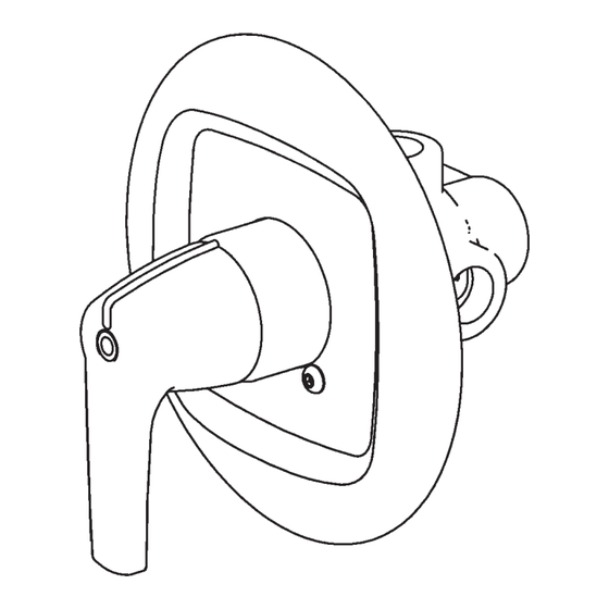
Bradley Thermostatic Mixing
Valve for Individual Showers
Table of Contents
Supplies Required. . . . . . . . . . . . . . . . . 2
Installation Instructions . . . . . . . . . . . . . . 2
Valve Adjustments. . . . . . . . . . . . . . . . . 3
Inlet Connections: 1/2" NPT
Outlet Connections: 1/2" NPT
Temperature Range: 90 – 110°F
Maximum Pressure: 125 PSIG
IMPORTANT!
P.O. Box 309, Menomonee Falls, WI USA 53052-0309
PHONE 800.BRADLEY (800.272.3539) FAX 262.251.5817
bradleycorp.com
Advertisement

Subscribe to Our Youtube Channel
Related Manuals for Bradley S59-2006


Summary of Contents for Bradley S59-2006
- Page 1 Product warranties may be found under “Products” on our web site at www.bradleycorp.com. 215-1296 Rev. E EN 10-09-010 P.O. Box 309, Menomonee Falls, WI USA 53052-0309 © 2012 Bradley PHONE 800.BRADLEY (800.272.3539) FAX 262.251.5817 Page 1 of 5 10/1/2012 bradleycorp.com...
- Page 2 • Rough-in 1/2" NPT hot and cold water supply piping (supplied by installer) as shown below. • For finished wall, make a 4-1/2" hole in the wall where the shower handle is desired. Bradley • 215-1296 Rev. E; EN 10-09-010 10/1/2012...
- Page 3 1/4" The included foam rim seal may be applied to the back of the escutcheon 1/4" from the outer edge, with the seam at the bottom. 1/4" Bradley • 215-1296 Rev. E; EN 10-09-010 10/1/2012...
- Page 4 Do not remove the seat. The components may be brushed with a small wire brush to remove debris. If the optional stop/check valves need to be replaced, contact your Bradley representative and ask for Stop/Check Valve (part number S27-292). Temperature The stop and check sections of the valve do not Clean Stop and Check Valves as described above.
-
Page 5: Parts Breakdown
Qty. Description Stem Screw Seal O-Ring O-Ring Seal O-Ring O-Ring Spring Thermostat Kit S65-201 Seal Screw Piston Item Qty. Description O-Ring Screw Spring Thermostat O-Ring Plate Retainer O-Ring O-Ring Nut, Hex Retaining Ring Bradley • 215-1296 Rev. E; EN 10-09-010 10/1/2012...
Need help?
Do you have a question about the S59-2006 and is the answer not in the manual?
Questions and answers