Goodwe MIS Series User Manual
Micro inverter
Hide thumbs
Also See for MIS Series:
- Quick installation manual (83 pages) ,
- Quick installation manual (2 pages)
Table of Contents
Advertisement
Quick Links
Advertisement
Table of Contents

Related Manuals for Goodwe MIS Series


Summary of Contents for Goodwe MIS Series
- Page 1 User Manual Micro Inverter V1.0-2023-07-30...
- Page 2 Copyright ©GoodWe Technologies Co.,Ltd. 2023. All rights reserved. No part of this manual can be reproduced or transmitted to the public platform in any form or by any means without the prior written authorization of GoodWe Technologies Co.,Ltd. Trademarks and other GOODWE trademarks are trademarks of GoodWe Technologies Co.,Ltd.
-
Page 3: Table Of Contents
CONTENT User Manual V1.0-2023-07-30 CONTENT 1 About This Manual ..............1 1.1 Applicable Model ..................1 1.2 Target Audience ...................1 1.3 Symbol Definition ..................2 1.4 Updates ......................2 2 Safety Precaution ..............3 2.1 General Safety .....................3 2.2 PV String Safety ...................3 2.3 AC Side ......................4 2.4 Inverter Safety .....................4 2.5 Personal Requirements ................5 2.6 EU Declaration of Conformity ..............5... - Page 4 User Manual V1.0-2023-07-30 CONTENT 6 Electrical Connection ............17 6.1 Safety Precaution ..................17 6.2 System Network Diagram ................ 17 6.3 Connecting the PE Cable ................18 6.4 Connecting the AC Output Cable ............19 6.5 Connecting the PV Input Cable ..............22 7 Equipment Commissioning ..........
-
Page 5: About This Manual
All the installers and users have to be familiar with the product features, functions, and safety precautions. This manual is subject to update without notice. For more product details and latest documents, visit https://en.goodwe.com/. 1.1 Applicable Model... -
Page 6: Symbol Definition
User Manual V1.0-2023-07-30 01 About This Manual 1.3 Symbol Definition Different levels of warning messages in this manual are defined as follows: DANGER Indicates a high-level hazard that, if not avoided, will result in death or serious injury. WARNING Indicates a medium-level hazard that, if not avoided, could result in death or serious injury. CAUTION Indicates a low-level hazard that, if not avoided, could result in minor or moderate injury. -
Page 7: Safety Precaution
• Strictly follow the installation, operation, and configuration instructions in this manual. The manufacturer shall not be liable for equipment damage or personal injury if you do not follow the instructions. For more warranty details, please visit https://en.goodwe.com/ warranty. 2.2 PV String Safety... -
Page 8: Ac Side
02 Safety Precaution User Manual V1.0-2023-07-30 2.3 AC Side WARNING • The voltage and frequency at the connection point meet the on-grid requirements. • Additional protective devices like circuit breakers or fuses are recommended on the AC side. Specification of the protective device should be at least 1.25 times the maximum AC output current. -
Page 9: Personal Requirements
2.6 EU Declaration of Conformity GoodWe Technologies Co., Ltd. hereby declares that the inverter with wireless communication modules sold in the European market meets the requirements of the following directives: • Radio Equipment Directive 2014/53/EU (RED) •... -
Page 10: Product Introduction
03 Product Introduction User Manual V1.0-2023-07-30 3 Product Introduction 3.1 Product Overview The MIS inverter is a micro single-phase grid-tied PV inverter. The inverter converts the DC power generated by the PV module into AC power and feeds it into the utility grid. The intended use of the inverter is as follows: PV string Utility grid... -
Page 11: Features
03 Product Introduction User Manual V1.0-2023-07-30 3.3 Features Module level monitoring The inverter supports 4 independent Maximum Power Point Tracking(MPPT for short). Each MPPT is connected to one PV module and tracks the maximum power point of each module. Power derating To satisfying the local laws or regulations and ensuring a safe operation, the inverter will automatically reduce the output power when the operating environment is not ideal. -
Page 12: Circuit Diagram
03 Product Introduction User Manual V1.0-2023-07-30 Inverter 1 WiFi Router Server SEMS Portal app/web WiFi WiFi Inverter 2 Inverter n Bluetooth < 5m The inverter can communicate with the EzLogger 3000R product for functions such as power limit, remote shutdown, etc. For more detailed instructions, refer to the user manual of EzLog- ger 3000R. -
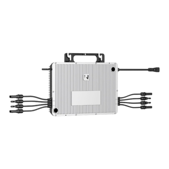
Page 13: Appearance
03 Product Introduction User Manual V1.0-2023-07-30 3.5 Appearance 3.5.1 Parts Parts Description Antenna Wireless communication; supports WiFi. Handle Moves or hangs the inverter. Connects grouding cables to the grouding points Grounding Point for protection. Connects the AC branch of the inverter to the trunk AC connector cable. -
Page 14: Indicators
03 Product Introduction User Manual V1.0-2023-07-30 3.5.3 Indicators Indicator status Descriptions Slow blinking green = Equipment on and in the standby mode. Fast blinking green = equipment starting and in the self-check mode. Steady green = The four PV inputs are available, and the invert- er is feeding power to the grid properly. -
Page 15: Check And Storage
04 Check and Storage User Manual V1.0-2023-07-30 4 Check and Storage 4.1 Check Before Receiving Check the following items before receiving the product. Check the outer packing box for damage, such as holes, cracks, deformation, and other signs of equipment damage. Do not unpack the package and contact the supplier as soon as possible if any damage is found. -
Page 16: Storage
04 Check and Storage User Manual V1.0-2023-07-30 4.3 Storage If the equipment is not to be installed or used immediately, please ensure that the storage environment meets the following requirements: 1. Do not unpack the outer package or throw the desiccant away. 2. -
Page 17: Installation
05 Installation User Manual V1.0-2023-07-30 5 Installation 5.1 Installation Requirements Installation Environment Requirements 1. Do not install the equipment in a place near flammable, explosive, or corrosive materials. 2. Install the equipment on a surface that is solid enough to bear the inverter weight. 3. - Page 18 05 Installation User Manual V1.0-2023-07-30 IP67 0%~100%RH Mounting Support Requirements • Install the inverter on the PV racking. • The mounting support shall be nonflammable and fireproof. • Ensure the PV racking is solid enough to bear the inverter weight. •...
-
Page 19: Inverter Installation
05 Installation User Manual V1.0-2023-07-30 Installation Tool Requirements The following tools are recommended when installing the equipment. Use other auxiliary tools on site if necessary. M8/M4 Torque wrench Goggles Safety shoes Safety gloves Dust mask Diagonal pliers Wire stripper Hammer drill Heat gun Cable tie Marker... -
Page 20: Installing The Inverter
05 Installation User Manual V1.0-2023-07-30 5.2.2 Installing the Inverter NOTICE • Plan the installation positions of the inverters and PV modules before installation. • Install the inverter on the rail. Prepare aluminum clamps to fix the installation screws when the holes on the rail are not suitable for installing the inverter. •... -
Page 21: Electrical Connection
User Manual V1.0-2023-07-30 06 Electrical Connection 6 Electrical Connection 6.1 Safety Precaution DANGER • Disconnect the PV connectors and the AC output switch of the inverter to power off the inverter before any electrical connections. Do not work with power on. Otherwise, an electric shock may occur. -
Page 22: Connecting The Pe Cable
User Manual V1.0-2023-07-30 06 Electrical Connection 6.3 Connecting the PE Cable WARNING • Both the grounding points on the enclosure and AC cable are recommended. • Make sure that all the grounding points on the enclosures are equipotential connected when there are multiple inverters. •... -
Page 23: Connecting The Ac Output Cable
User Manual V1.0-2023-07-30 06 Electrical Connection 6.4 Connecting the AC Output Cable WARNING Do not connect loads between the inverter and the AC switch directly connected to the inverter. An AC circuit breaker shall be installed on the AC side to make sure that the inverter can safely disconnect the grid when an exception happens. - Page 24 User Manual V1.0-2023-07-30 06 Electrical Connection The number of micro inverters on each AC branch shall not exceed the limit below. Specification of the T Maximum number per branch Over Current shape AC connector/ Protection Device Specification of the GW1600-MIS GW1800-MIS GW2000-MIS (OCPD)
- Page 25 User Manual V1.0-2023-07-30 06 Electrical Connection 0.7-0.9N·m A sealing plug is required as below when there is no AC cable connected at the end of the system. 0.7-0.9N·m...
-
Page 26: Connecting The Pv Input Cable
User Manual V1.0-2023-07-30 06 Electrical Connection 6.5 Connecting the PV Input Cable DANGER 1. Confirm the following information before connecting the PV module to the inverter. Otherwise, the inverter may be damaged permanently or even cause fire and cause personal and property losses. - Page 27 User Manual V1.0-2023-07-30 06 Electrical Connection 7-8mm Φ: 4-5mm 7-8mm ≤S≤6mm Click ≤65V...
-
Page 28: Equipment Commissioning
07 Equipment Commissioning User Manual V1.0-2023-07-30 7 Equipment Commissioning 7.1 Check Before Power ON Check Item The product is firmly installed at a clean place that is well-ventilated and easy-to operate. The PE, PV input, and AC output cables are connected correctly and securely. Cable ties are intact, routed properly and evenly. -
Page 29: System Commissioning
08 System Commissioning User Manual V1.0-2023-07-30 8 System Commissioning 8.1 Indicators Indicator status Description Slow blinking green = Equipment on and in the standby mode. Fast blinking green = equipment starting and in the self-check mode. Steady green = The four PV inputs are available, and the inverter is feeding power to the grid properly. -
Page 30: Setting Inverter Parameters Via App
1. Check the operating data, software version, alarms, etc. 2. Set grid parameters, communication parameters, etc. 3. Equipment maintenance. Visit https://en.goodwe.com or scan the QR code to read the user manual. SolarGo APP SolarGo APP User Manual 8.4 Monitoring via SEMS Portal SEMS Portal is a monitoring platform used to communicate with the inverter via WiFi, LAN, 4G, or GPRS. -
Page 31: Maintenance
09 Maintenance User Manual V1.0-2023-07-30 9 Maintenance 9.1 Power Off the Inverter DANGER • Power off the inverter before operations and maintenance. Otherwise, the inverter may be damaged or electric shocks may occur. • Delayed discharge. Wait until the components are discharged after power off. Step 1 (optional) Send shutdown command to the inverter. -
Page 32: Troubleshooting
09 Maintenance User Manual V1.0-2023-07-30 9.4 Troubleshooting Perform troubleshooting according to the following methods. Contact the after-sales service if these methods do not work. Collect the information below before contacting the after-sales service, so that the problems can be solved quickly. 1. - Page 33 09 Maintenance User Manual V1.0-2023-07-30 Fault Cause Solutions 1. If the problem occurs occasionally, the utility grid may be abnormal temporarily. The inverter will recover automatically after detecting that the utility grid is normal. 2. If the problem occurs frequently, check whether the grid voltage is within the The grid voltage is Grid Rapid...
- Page 34 09 Maintenance User Manual V1.0-2023-07-30 Fault Cause Solutions 1. If the problem occurs occasionally, the utility grid may be abnormal temporarily. The inverter will recover automatically after detecting that the utility grid is normal. The moving 2. If the problem occurs frequently, check average of grid whether the grid voltage is within the Grid 10min...
- Page 35 09 Maintenance User Manual V1.0-2023-07-30 Fault Cause Solutions 1. If the problem occurs occasionally, the utility grid may be abnormal temporarily. The inverter will recover automatically after detecting that the utility grid is normal. Utility grid 2. If the problem occurs frequently, check exception.
- Page 36 09 Maintenance User Manual V1.0-2023-07-30 Fault Cause Solutions Utility grid exception. The 1. If the problem occurs occasionally, the duration of LVRT utility grid may be abnormal temporarily. the utility grid Undervoltage The inverter will recover automatically exception exceeds after detecting that the utility grid is the set time of normal.
- Page 37 09 Maintenance User Manual V1.0-2023-07-30 Fault Cause Solutions 1. If the exception is caused by an external fault, the inverter will recover Anti Reverse Abnormal automatically after solving the problem. 2. If the problem occurs frequently and the power Failure fluctuation of load PV station cannot work properly, contact the dealer or the after-sales service.
-
Page 38: Routine Maintenance
09 Maintenance User Manual V1.0-2023-07-30 9.5 Routine Maintenance DANGER Power off the inverter before operations and maintenance. Otherwise, the inverter may be damaged or electric shocks may occur. Maintaining Item Maintaining Method Maintaining Period Check the heat sink for foreign matter or System Clean Once 6-12 months dust. -
Page 39: Technical Parameters
User Manual V1.0-2023-07-30 10 Technical Parameters 10 Technical Parameters Technial Data GW1600-MIS GW1800-MIS GW2000-MIS Input Max. Input Power (W) 2160 2430 2700 Max. Input Voltage (V) MPPT Operating Voltage Range (V) 16~60 16~60 16~60 MPPT Voltage Range at Nominal 27~60 30~60 33~60 Power (V) - Page 40 User Manual V1.0-2023-07-30 10 Technical Parameters Technial Data GW1600-MIS GW1800-MIS GW2000-MIS Maximum Output Overcurrent Protection (A) Efficiency Max. Efficiency 96.4% 96.4% 96.4% European Efficiency 94.0% 94.0% 94.0% Protection PV String Current Monitoring Integrated Integrated Integrated PV Insulation Resistance Detection Integrated Integrated Integrated PV Reverse Polarity Protection...
- Page 41 User Manual V1.0-2023-07-30 10 Technical Parameters Technial Data GW1600-MIS GW1800-MIS GW2000-MIS PV: C PV: C PV: C The Decisive Voltage Class (DVC) AC: C AC: C AC: C COM: A COM: A COM: A Active Anti-islanding Method AFDPF + AQDPF AFDPF + AQDPF AFDPF + AQDPF Country of Manufacture...
-
Page 42: Appendix
11 Appendix User Manual V1.0-2023-07-30 11 Appendix Installation Map Reference... - Page 43 Official Website GoodWe Technologies Co.,Ltd. No. 90 Zijin Rd., New District, Suzhou, 215011, China www.goodwe.com service@goodwe.com Local Contacts...
Need help?
Do you have a question about the MIS Series and is the answer not in the manual?
Questions and answers