Goodwe MT Series User Manual
Solar inverter
Hide thumbs
Also See for MT Series:
- User manual (17 pages) ,
- Introduction manual (69 pages) ,
- Quick installation manual (2 pages)
Table of Contents
Advertisement
SolarGo App
SEMS Portal App
LinkedIn
GOODWE (Germany)
Fürstenrieder Str. 279a 81377 München, Germany
T: +49 8974120210 +49 421 83570-170 (service)
sales.de@goodwe.com
service.de@goodwe.com
GOODWE (Netherlands)
Franciscusdreef 42C, 3565AC Utrecht, the Netherlands
T: +31 (0) 30 737 1140
sales@goodwe.com
service.nl@goodwe.com
GOODWE (India)
1202, G-Square Business Park, Sector 30A, Opp. Sanpada
Railway Stn., Vashi, Navi Mumbai- 400703
T: +91 (0) 2249746788
sales@goodwe.com / service.in@goodwe.com
GOODWE (Turbutton)
Adalet Mah. Megapol Tower K: 9 No: 110 Bayraklı - Izmir
T: +90 (232) 935 68 18
info@goodwe.com.tr
service@goodwe.com.tr
GOODWE (Mexico)
Oswaldo Sanchez Norte 3615, Col. Hidalgo, Monterrey,
Nuevo Leon, Mexico, C.P. 64290
T: +52 1 81 2871 2871
sales@goodwe.com / soporte.latam@goodwe.com
Note: The information above is subject to change without prior notice, for details refer to
www.goodwe.com
Company's Offical
Website
GOODWE (China)
No. 90 Zijin Rd., New District, Suzhou, 215011, China
T: +86 (0) 512 6958 2201
sales@goodwe.com (sales)
service@goodwe.com (service)
GOODWE (Brazil)
Rua Abelardo 45, Recife/PE, 52050-310
T: +55 81 991239286
sergio@goodwe.com
servico.br@goodwe.com
GOODWE (UK)
6 Dunhams Court, Dunhams Lane, Letchworth
Garden City, SG6 1WB UK
T:+ 44 (0) 333 358 3184
enquiries@goodwe.com.uk / service@goodwe.com.uk
GOODWE (Italy)
Via Cesare Braico 61, 72100 Brindisi, Italy
T: +39 338 879 38 81; +39 831 162 35 52
valter.pische@goodwe.com (sales)
operazioni@topsenergy.com; goodwe@arsimp.it (service)
GOODWE (Australia)
Level 14, 380 St. Kilda Road, Melbourne,
Victoria, 3004, Australia
T: +61 (0) 3 9918 3905
sales@goodwe.com / service.au@goodwe.com
GOODWE (Korea)
8F Invest Korea Plaza, 7 Heoleung-ro
Seocho-gu Seoul Korea (06792)
T: 82 (2) 3497 1066
sales@goodwe.com / Larry.Kim@goodwe.com
MT SERIES USER MANUAL
SOLAR INVERTER
Version 1.0
Advertisement
Table of Contents

Related Manuals for Goodwe MT Series


Summary of Contents for Goodwe MT Series
- Page 1 GOODWE (China) No. 90 Zijin Rd., New District, Suzhou, 215011, China T: +86 (0) 512 6958 2201 sales@goodwe.com (sales) service@goodwe.com (service) MT SERIES USER MANUAL GOODWE (Germany) GOODWE (Brazil) Fürstenrieder Str. 279a 81377 München, Germany Rua Abelardo 45, Recife/PE, 52050-310...
-
Page 2: Table Of Contents
1 Symbols ..........................2 Safety Measures & Warning ............... 3 Product Introduction ..................3.1 Intended Usage .......................... 04 3.2 Inverter Overview ........................05 3.3 Technical Description ........................ 07 3.4 Package ............................08 4 Installation ........................4.1 Mounting Instructions ....................... 09 4.2 Equipment Installation ...................... -
Page 3: Symbols
1 Symbols 2 Safety Measures & Warning This manual contains important instructions for MT series of inverter which must be followed Failure to observe a warning indicated in this manual may result in during installation and maintenance. injury. The MT series includes Four-MPPT, Three-Phase solar inverter without transformer which con-... -
Page 4: Product Introduction
• Static electricity may damage electronic components. Appropriate measures must be adopted The MT series which is a Four MPPT, three phase transformer-less grid-connected inverter which to prevent such damage to the inverter; otherwise the inverter may be damaged and the warran- is a crucial unit between the PV string and the utility grid in the PV power system. -
Page 5: Inverter Overview
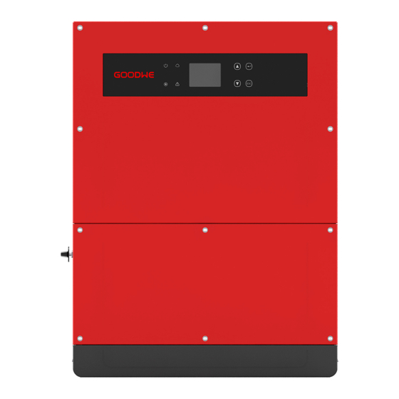
GW70KHV-MT / GW80KHV-MT and GW80KBF-MT support IT grid type. Refer to below figure. Without LCD Transformer Inverter 3.2 Inverter Overview MT series inverter illustration. Note: Image shown here is for reference only, actual product you receive may be different. 1. PV Input Terminal 5. GPRS Port (Optional) 8. Indicator Light 2. -
Page 6: Technical Description
PV string voltage is transmitted to DC BUS via BOOST circuit. 1. Check the package for any visible damage upon receiving. The MT series is equipped with four MPPTs for four DC inputs to ensure that the maximum power is utilized even in different PV installation condition. -
Page 7: Installation
4 Installation To ensure heat dissipation and convenient disassembly, the minimum clearance around the inverter should not be less than the following values. 4.1 Mounting Instructions 1. In order to achieve optimal performance, the ambient temperature should be lower than 45℃. 200mm 2. -
Page 8: Electrical Connection
4.2.3 Schematic Diagram Of Cover Dismantling And Installation Steps 7. Neutral conductor shall be blue, line conductor shall be black or brown (preferred), protective earth bonding line shall be yellow-green. 1. Dismantle the downside cover. 2. Electrical installation. 8. The AC line construction shall be such that if the cord should slip from its anchorage, placing a (Tool: external hexagonal screwdriver) strain on conductors, the protective earthing conductor will be the last to take the strain. - Page 9 8. The MT series has four PV input area PV1 input, PV2 input, PV3 input, PV4 input, each with MPP tracker. The four PV input works independently, therefore the four PV input can be different with...
-
Page 10: Communication Connection
The inverter works automatically when the input and output meet the requirements. Rotating The connection steps of RS485 communication of MT series are as follows: the DC switch to "OFF" position will immediately cut off the flow of DC current. - Page 11 RS485+ After the configurations are completed, please register on the website www.goodwe.com. RS485- Please refer to WiFi app for specific configuration. Reserved 6.5mm The WiFi module installation of MT series are shown as below. Reserved RS485+ RS485- 25mm Step 3: Connect the terminal to the right position onto the inverter.
-
Page 12: System Operation
5 System Operation Step2: 1. Plug out the 4-pin terminal and dismantle the resistor on it. 5.1 LCD Panel And LED 2. Plug the wire out, leave the 4-pin terminal for next step. As a human-computer interaction interface, LCD display panel comprises of LED indicators, buttons and LCD display on the front panel of the inverter. -
Page 13: User Interface Introduction
Press the "Enter" / "ESC" to enter / exit the each level menu, use the "Up" / "Down" to select the NOTE: item and change the parameters, and long press the "Enter" (greater than 3s) to set the Download SolarGo App from Google Play Store or Apple App Store to parameters. -
Page 14: System Configuration
5.3 System Configuration 5.3.2 First Level Menu Press "up" / "down" to select on the inerface of First Level: History, Configuration, Adv.Settings etc. 5.4.1 Basic Settings Pressing the Enter button will enter corressponding Second Level menu. Select the item through Basic settings is mainly used to set the commonly used parameters, including language settings, the "up"... - Page 15 5.4.3 History Information The history information is mainly included in the information of the generating capacity of the Adv.Settings Adv.Settings Adv.Settings Adv.Settings Enter Enter Enter equipment, the fault record, the power generation information. The power generation informa- LVRT LVRT LVRT LVRT Shadow Shadow...
-
Page 16: Wi-Fi Reset & Wi-Fi Reload
5.4 Wi-Fi Reset & Wi-Fi Reload menu. The interface displays current state of the system. It shows "Waiting" when in the initial state; it shows "Normal" when in the power generation mode; if there is something wrong with These functions are only available for Wi-Fi model inverters. the system, error message will be shown. -
Page 17: Special Adjustable Setpoints
6 Troubleshooting Error code Error message Description If the Inverter is not able to work properly, please refer to the following instructions before The DC component of AC current exceed DC Injection High contacting your local service. If any problems arise, the red (FAULT) LED indicator on the front inverter's limit panel will light up and the LCD screen will display relevant information. -
Page 18: Technical Parameters & Block Diagram
7 Technical Parameters & Block Diagram Type of fault Troubleshooting 7.1 Technical Parameters Relay-Check Failure Technical Data GW30KLV-MT GW35KLV-MT GW50KLV-MT DCI Injection High DC Input Data Max. PV Power (W) 54000 63000 90000 EEPROM R/W Failure Max. DC Input Voltage (V) SCI Failure MPPT Range (V) 200~650... - Page 19 Technical Data GW50KN-MT GW60KN-MT GW50KBF-MT Technical Data GW60KBF-MT GW75KBF-MT GW80KBF-MT DC Input Data DC Input Data 80000 97500 104000 Max. PV Power (W) 65000 80000 65000 Max. PV Power (W) Max. DC Input Voltage (V) 1100 1100 1100 Max. DC Input Voltage (V) 1100 1100 1100...
- Page 20 Technical Data GW70KHV-MT GW80KHV-MT Technical Data GW75K-MT GW80K-MT DC Input Data DC Input Data Max. PV Power (W) 112500 120000 Max. PV Power (W) 91000 120000 Max. DC Input Voltage (V) 1100 1100 Max. DC Input Voltage (V) 1100 1100 MPPT Range (V) 200~1000 200~1000...
-
Page 21: Block Diagram
7.2 Block Diagram Note: Overvoltage Category Definition GW30KLV-MT / GW50KN-MT main circuit. Category I: applies to equipment connected to a circuit where measures have been taken to reduce transient overvoltage to a low level. Input PV1+ MPPT Circuit 1 PV1- Filter Category II: applies to equipment not permanently connected to the installation. -
Page 22: Caution
MPPT AC SPD PV3- Circuit 3 Filter MT series inverter is equipped with three fans on its left side. The fan intakes and handle covers AC Relay PV4+ Input MPPT should be cleaned yearly with a vacuum cleaner. For more thorough cleaning, completely... -
Page 23: Turn On/Off The Inverter
8.3 Turn On/Off The Inverter Boot order: 1. Turn on the breaker on AC side. 2. Turn on the DC switch. 3. Turn on the breaker on DC side. Note: If there's no switch, only need to do step 1 and step 3(please skip step 2). Shutdown order: 1.
Need help?
Do you have a question about the MT Series and is the answer not in the manual?
Questions and answers