Table of Contents
Advertisement
SolarGo App
SEMS Portal App
LinkedIn
GOODWE (Germany)
Fürstenrieder Str. 279a 81377 München, Germany
sales.de@goodwe.com
service.de@goodwe.com
GOODWE (Netherlands)
Franciscusdreef 42C, 3565AC Utrecht, the Netherlands
sales@goodwe.com
service.nl@goodwe.com
GOODWE (India)
1202, G-Square Business Park, Sector 30A, Opp. Sanpada
Railway Stn., Vashi, Navi Mumbai- 400703
sales@goodwe.com / service.in@goodwe.com
GOODWE (Turbutton)
Adalet Mah. Megapol Tower K: 9 No: 110 Bayraklı - Izmir
info@goodwe.com.tr
service@goodwe.com.tr
GOODWE (Mexico)
Oswaldo Sanchez Norte 3615, Col. Hidalgo, Monterrey,
Nuevo Leon, Mexico, C.P. 64290
sales@goodwe.com / soporte.latam@goodwe.com
Note: The information above is subject to change without prior notice, for details refer to
www.goodwe.com
Offical Website
GOODWE (China)
No. 90 Zijin Rd., New District, Suzhou, 215011, China
T: 400-998-1212
sales@goodwe.com (sales)
service@goodwe.com (service)
GOODWE (Brazil)
Rua Abelardo 45, Recife/PE, 52050-310
sergio@goodwe.com
servico.br@goodwe.com
GOODWE (UK)
6 Dunhams Court, Dunhams Lane, Letchworth
Garden City, SG6 1WB UK
enquiries@goodwe.com.uk / service@goodwe.com.uk
GOODWE (Italy)
Via Cesare Braico 61, 72100 Brindisi, Italy
valter.pische@goodwe.com (sales)
operazioni@topsenergy.com; goodwe@arsimp.it (service)
GOODWE (Australia)
Level 14, 380 St. Kilda Road, Melbourne,
Victoria, 3004, Australia
sales@goodwe.com / service.au@goodwe.com
GOODWE (Korea)
8F Invest Korea Plaza, 7 Heoleung-ro
Seocho-gu Seoul Korea (06792)
sales@goodwe.com / Larry.Kim@goodwe.com
340-00566-01
MT G2 SERIES USER MANUAL
SOLAR INVERTER
Ver 2.0
2021-08-20
Advertisement
Table of Contents

Related Manuals for Goodwe MT G2 Series


Summary of Contents for Goodwe MT G2 Series
- Page 1 Offical Website GOODWE (China) No. 90 Zijin Rd., New District, Suzhou, 215011, China T: 400-998-1212 sales@goodwe.com (sales) service@goodwe.com (service) MT G2 SERIES USER MANUAL GOODWE (Germany) GOODWE (Brazil) Fürstenrieder Str. 279a 81377 München, Germany Rua Abelardo 45, Recife/PE, 52050-310 sales.de@goodwe.com sergio@goodwe.com...
-
Page 2: Table Of Contents
1 Symbols ..........................2 Safety Measures & Warning ............... 3 Product Introduction ..................3.1 Intended Usage .......................... 04 3.2 Inverter Overview ........................05 3.3 Technical Description ........................ 07 3.4 Package ............................08 4 Installation ........................4.1 Mounting Instructions ....................... 09 4.2 Equipment Installation ...................... -
Page 3: Symbols
1 Symbols 2 Safety Measures & Warning This manual contains important instructions for the MT series of inverter which must be followed Failure to observe warnings indicated in this manual may result in during installation and maintenance. injury. The MT series includes four MPPTs and a Three-Phase solar inverter without transformer which consists of GW30KLV-MT / GW35KLV-MT / GW50KLV-MT / GW50KN-MT / GW50KBF-MT / GW50KBF-MT-KR / GW60KBF-MT-KR / GW60KN-MT / GW60KBF-MT /GW75KBF-MT / GW70KHV-MT Recyclable materials... -
Page 4: Product Introduction
MT series GW30KLV-MT / GW35KLV-MT / GW50KLV-MT / GW50KN-MT / GW50KBF-MT-KR / GW60KBF-MT-KR / GW60KN-MTV / GW50KBF-MT / GW60KBF-MT / GW75K-MT / GW80K-MT To our inverter product, GOODWE provides a standard manufacturer's warranty, which comes support four different types of grid. -
Page 5: Inverter Overview
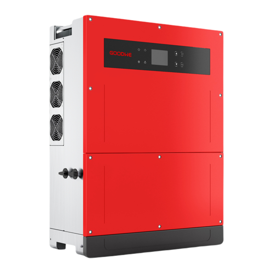
GW70KHV-MT / GW80KHV-MT and GW80KBF-MT support the IT grid type. Refer to the below figure. GW60KBF-MT/GW75KBF-MT/GW80KBF-MT/GW80KHV-MT/GW75K-MT/GW80K-MT Transformer Inverter 3.2 Inverter Overview MT series inverter illustration. Note: Image shown here is for reference only; actual product you receive may be different. 1. -
Page 6: Technical Description
3.3 Technical Description 3.4 Package 3.3.1 Principle Description The unit is thoroughly tested and strictly inspected before delivery. Damage may occur during shipping. PV string voltage is transmitted to DC BUS via BOOST circuit. 1. Check the package for any visible damage upon receipt. The MT series is equipped with four MPPTs for four DC inputs to ensure that the maximum power is utilized even in different PV installation configurations. -
Page 7: Installation
4 Installation To ensure heat dissipation and convenient disassembly, the minimum clearance around the inverter should not be less than the following values: 4.1 Mounting Instructions 1. To achieve optimal performance, the ambient temperature should be lower than 45℃. 200mm 2. -
Page 8: Electrical Connection
4.2.3 Schematic of Cover Dismantling and Installation Steps 7. Neutral conductor shall be blue; line conductor shall be black or brown (preferred); protective earth bonding line shall be yellow-green. 1. Dismantle the downside cover. 2. Electrical installation. 8. The AC line construction shall be such that if the cord should slip from its anchorage, placing a (Tool: external hexagonal screwdriver) strain on conductors, the protective earthing conductor will be the last to take the strain. - Page 9 The output current of GW50KLV-MT / GW50KLV-MT / GW80K-MT is 133A. Thus, we recommend 4.3.4 Connecting Inverter to PV Panel that the nominal current of the AC breaker should be more than 160A. Caution Note: It is not allowed for several inverter to use the same circuit breaker. Connecting loads between the inverter and circuit breaker is also not allowed 1.
-
Page 10: Communication Connection
The installation method for DC connector. Positive connector Inverter side Negative connector 2. Insert the USB data cable 1. Open the bottom cover MC4 & QC4.10 DEVALAN & AMPHENOL This function is only for local firmware upgrades and parameter calibrations. Do not crimp wire into the limit buckle. - Page 11 This function is only applicable for Wi-Fi model inverter. Please refer to 'Wi-Fi Configuration Instruction' to complete WiFi configuration. Function RS485+ After the configurations are completed, please register on the website: www.goodwe.com. RS485- Please refer to Wi-Fi app for specific configuration. Reserved 6.5mm...
-
Page 12: System Operation
5 System Operation Step2: 1. Plug out the 4-pin terminal and dismantle the resistor on it. 5.1 LCD Panel and LED 2. Plug the wire out; leave the 4-pin terminal for the next step. As a human-computer interaction interface, the LCD display panel comprises LED indicators, buttons and adisplay on the front panel of the inverter. -
Page 13: User Interface Introduction
Press the 'Enter' / 'ESC' to enter / exit the each level menu, use the 'Up' / 'Down' to select the NOTE: item and change the parameters, and long press the 'Enter' (greater than 3s) to set the parame- Download SolarGo App from Google Play Store or Apple Store to ters. -
Page 14: System Configuration
5.3 System Configuration 5.3.2 First-level Menu Press 'up' / 'down' to select on the interface of First-level: History, Configuration, Adv.Settings etc. 5.4.1 Basic Settings Pressing the Enter button will enter corressponding Second-level menu. Select the item through Basic settings are mainly used to set the commonly used parameters, including language the 'up' / 'down' in Second-level menu. - Page 15 5.4.3 History Information The history information mainly includes in the information about the generating capacity of the Adv.Settings Adv.Settings Adv.Settings Adv.Settings equipment, the fault record, the power generation information. The power generation informa- Enter Enter Enter LVRT LVRT LVRT LVRT Shadow Shadow Shadow...
-
Page 16: Wi-Fi Reset & Wi-Fi Reload
5.4.5 Menu Introduction 5.4 Wi-Fi Reset & Wi-Fi Reload When PV panel is feeding power to the inverter, the screen shows the first interface of the These functions are only available for Wi-Fi model inverters. first-level menu. The interface displays current state of the system. It shows 'Waiting' when in the 1. -
Page 17: Special Adjustable Setpoints
6 Troubleshooting Error code Error message Description If the Inverter is unable to work properly, please refer to the following instructions before The DC component of AC current exceed DC Injection High contacting your local service centre. If any problems arise, the red (FAULT) LED indicator on the inverter's limit front panel will light up and the LCD screen will display relevant information. -
Page 18: Technical Parameters & Block Diagram
7 Technical Parameters & Block Diagram Type of fault Troubleshooting 7.1 Technical Parameters Relay-Check Failure Technical Data GW30KLV-MT GW35KLV-MT GW50KLV-MT DCI Injection High DC Input Data 54000 63000 90000 EEPROM R/W Failure Max. PV Power (W) Max. DC Input Voltage (V) SCI Failure MPPT Range (V) 200~650... - Page 19 Technical Data GW60KBF-MT GW75KBF-MT GW80KBF-MT Technical Data GW50KN-MT GW60KN-MT GW50KBF-MT DC Input Data DC Input Data Max. PV Power (W) Max. PV Power (W) 80000 97500 104000 65000 80000 65000 Max. DC Input Voltage (V) 1100 1100 1100 Max. DC Input Voltage (V) 1100 1100 1100...
- Page 20 Technical Data GW70KHV-MT GW80KHV-MT Technical Data GW75K-MT GW80K-MT DC Input Data DC Input Data Max. PV Power (W) Max. PV Power (W) 91000 120000 112500 120000 Max. DC Input Voltage (V) 1100 1100 Max. DC Input Voltage (V) 1100 1100 MPPT Range (V) 200~1000 200~1000...
- Page 21 Note: Technical Data GW50KBF-MT-KR GW60KBF-MT-KR Input Overvoltage Category Definition Max. Input Power (W) 65000 80000 Max. Input Voltage (V) 1100 1100 Category I: applies to equipment connected to a circuit where measures have been taken to MPPT Operating Voltage Range (V) 200~1000 200~1000 reduce transient overvoltage to a low level.
-
Page 22: Block Diagram
7.2 Block Diagram GW70KHV-MT / GW80KBF-MT main circuit. GW30KLV-MT / GW50KN-MT main circuit. Input PV1+ MPPT Circuit 1 PV1- Filter Input Input PV1+ PV2+ MPPT MPPT Circuit 1 Circuit 2 PV1- PV2- Output Filter Filter DC / AC Converter Switch Filter Filter Filter... -
Page 23: Caution
8 Caution 8.3 Turn On / Off the Inverter Boot order: Regular maintenance ensures a long operating life and optimal efficiency of the entire PV plant. 1. Turn on the breaker on the AC side. Caution: Before maintenance, please first disconnect the AC breaker. Then disconnect the DC breaker.
Need help?
Do you have a question about the MT G2 Series and is the answer not in the manual?
Questions and answers