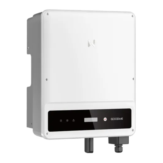
Goodwe MS Series User Manual
Solar inverter
Hide thumbs
Also See for MS Series:
- User manual (60 pages) ,
- Quick installation manual (20 pages) ,
- Quick installation manual (2 pages)
Table of Contents
Advertisement
SEMS Portal APP
LinkedIn
SEMS Portal website
www.semsportal.com
GoodWe (Germany)
Fürstenrieder Str. 279a 81377 München, Germany
T: +49 8974120210 +49 421 83570-170 (service)
sales.de@goodwe.com
service.de@goodwe.com
GoodWe (Netherlands)
Franciscusdreef 42C, 3565AC Utrecht, the Netherlands
T: +31 (0) 30 737 1140
sales@goodwe.com
service.nl@goodwe.com
GoodWe (India)
1202, G-Square Business Park, Sector 30A, Opp. Sanpada
Railway Stn., Vashi, Navi Mumbai- 400703
T: +91 (0) 2249746788
sales@goodwe.com / service.in@goodwe.com
GoodWe (Turkey)
Adalet Mah. Megapol Tower K: 9 No: 110 Bayraklı - Izmir
T: +90 (232) 935 68 18
info@goodwe.com.tr
service@goodwe.com.tr
GoodWe (Mexico)
Oswaldo Sanchez Norte 3615, Col. Hidalgo, Monterrey,
Nuevo Leon, Mexico, C.P. 64290
T: +52 1 81 2871 2871
sales@goodwe.com / soporte.latam@goodwe.com
Note: The information above is subject to change without prior motice, details refer to www.goodwe.com
Company's
offical website
GoodWe (China)
No. 90 Zijin Rd., New District, Suzhou, 215011, China
T: +86 (0) 512 6958 2201
sales@goodwe.com (sales)
service@goodwe.com (service)
GoodWe (Brazil)
Rua Abelardo 45, Recife/PE, 52050-310
T: +55 81 991239286
sergio@goodwe.com
servico.br@goodwe.com
GoodWe (UK)
6 Dunhams Court, Dunhams Lane, Letchworth
Garden City, SG6 1WB UK
T:+ 44 (0) 333 358 3184
enquiries@goodwe.com.uk / service@goodwe.com.uk
GoodWe (Italy)
Via Cesare Braico 61, 72100 Brindisi, Italy
T: +39 338 879 38 81; +39 831 162 35 52
valter.pische@goodwe.com (sales)
operazioni@topsenergy.com; goodwe@arsimp.it (service)
GoodWe (Australia)
Level 14, 380 St. Kilda Road, Melbourne,
Victoria, 3004, Australia
T: +61 (0) 3 9918 3905
sales@goodwe.com / service.au@goodwe.com
GoodWe (Korea)
8F Invest Korea Plaza, 7 Heoleung-ro
Seocho-gu Seoul Korea (06792)
T: 82 (2) 3497 1066
sales@goodwe.com / Larry.Kim@goodwe.com
MS SERIES USER MANUAL
SOLAR INVERTER
Version 1.0.1
Advertisement
Table of Contents

Related Manuals for Goodwe MS Series


Summary of Contents for Goodwe MS Series
- Page 1 Nuevo Leon, Mexico, C.P. 64290 Seocho-gu Seoul Korea (06792) T: +52 1 81 2871 2871 T: 82 (2) 3497 1066 sales@goodwe.com / soporte.latam@goodwe.com sales@goodwe.com / Larry.Kim@goodwe.com Version 1.0.1 Note: The information above is subject to change without prior motice, details refer to www.goodwe.com...
-
Page 2: Table Of Contents
1 Symbols ..........................2 Safety Measures & Warning ............... 3 Product Introduction ..................3.1 Inverter Overview ........................03 3.2 Package ............................03 4 Installation ........................4.1 Mounting Instructions ....................... 04 4.2 Equipment Installation ......................04 4.3 Electrical Connection ........................ 06 4.4 Communication Connection .................... -
Page 3: Symbols
1 Symbols 2 Safety measures & warning The MS series inverter of Jiangsu GoodWe Power Technolgy Co., Ltd. (hereinafter referred to as GoodWe) strictly conforms to related safety rules in design and test. Risk of injury due to improper handling of the device Safety regulation relevant to the location shall be followed during installation, commissioning, operation and maintenance. -
Page 4: Product Introduction
3 Product introduction 4 Installation 4.1 Mounting instructions 3.1 Inverter Overview Please refer as below. • In order to achieve optimal performance, the ambient temperature should be lower than 45℃. • For easy maintenance, we suggest to install the inverter at eye level. •... -
Page 5: Electrical Connection
4.3 Electrical Connection For dissipation of heat and convenience of dismantling, clearnaces around the inverter must meet the standard as shown below : 4.3.1 Connection to grid (AC side Connection) The installation position should not prevent access to the disconnection means. 1. - Page 6 6. Positive cable shall be red, negative cable shall be black. Inverter Conductor core section 7. The minimum insulation resistance to ground of the PV panels for MS series must exceed 33.4K GW5000-MS/GW6000MS/GW7000-MS/GW8500MS Ω(R=1000/30mA).There is a risk of shock hazard if the requirements of minimum resistance are...
-
Page 7: Communication Connection
4.4 Communication connection The connection steps of RS485 communication of MS series are as follows: Inverter operation data can be transferred by USB, RS485 or WIFI Modular to a PC with monitor- Step 1: Screw this plate off from inverter. - Page 8 4.4.3 Wi-Fi/LAN Communication The connection steps of DRED /Remote Shutdown& CTcommunication of MS series as follows: The Wi-Fi/LAN communication function is only applicable if the inverter has a WiFi module.The Step 1: Screw this plate off from inverter. detailed configuration instruction please refer to Wi-Fi Configuration/LAN Module Quick Installa- tion Guide in the accessory box.After configuration, please browse http://www.goodwe-pow-...
-
Page 9: System Operation
5 System Operation Step 3: Connect the terminal to the right position onto the inverter and screw the plate. 5.1 Indicator Lights 1. Supported DRM command: DRM0, DRM5, DRM6, DRM7, DRM8. Inverter with LCD, indicator lights in Yellow/Green/Red correspondently refer to 2. - Page 10 2. Display area First Level Menu Second Level Menu Normal Long Press Line 1---Working status information 50Hz Grid Default Pac=6000W Short Press Line 2---Diaplays of the real-time power generated by the inverter. E-Today=15.2KWh Long Press Lock Pac=6000W This area displays the status information. "Waiting Pac=0.0W" indicates the inverter is Short Press E-Total=533.17KWh standing by for power generation;...
- Page 11 • Short press the button to enter the menu which displays the PV3 voltage in "V" and current in Short press to change the number in current location, and long press (2s) to move the cursor "A". to next position. The inverter will store the time if there is no input over 20 seconds, and the LCD will automatically return to the main menu and the backlight will switch off.
-
Page 12: Error Message
6 Troubleshooting 6. Operation of display under grid-connected mode. When the input voltage reaches the inverter's turn-on voltage, the LCD starts to work, the If the Inverter is not able to work properly, please refer to the following instructions before yellow light will be turned on and the LCD will display "Waiting". -
Page 13: Technical Parameters
7 Technical Parameters Type of fault Troubleshooting Relay-Check Failure Technical Data GW5000-MS GW6000-MS GW7000-MS GW8500-MS GW10K-MS PV Input Data DCI Injection High Max. DC Input Power (Wp) 10000 12000 13500 13500 13500 Inverter 1. Disconnect the DC connector and AC. Max. - Page 14 Note: Overvoltage category definition Category I: applies to equipment connected to a circuit where measures have been taken to reduce transient overvoltage to a low level. Category II: applies to equipment not permanently connected to the installation. For example, appliances, portable tools and other plug-connected equipment;...
Need help?
Do you have a question about the MS Series and is the answer not in the manual?
Questions and answers