Goodwe MS Series Quick Installation Manual
Grid-tied pv inverter
Hide thumbs
Also See for MS Series:
- User manual (60 pages) ,
- Quick installation manual (2 pages) ,
- Quick installation manual (105 pages)

Subscribe to Our Youtube Channel
Related Manuals for Goodwe MS Series


Summary of Contents for Goodwe MS Series
- Page 1 Quick Installation Guide Grid-Tied PV Inverter MS Series (GW5000-MS-US30 GW6000-MS-US30 GW7600-MS-US30 |GW7700-MS-US30| GW9600-MS-US30 GW11K4-MS-US30) V1.1-2022-11-30...
- Page 2 TABLE OF CONTENTS EN ........................1 ES ........................4 Introduction ....................7...
-
Page 3: Safety Disclaimer
• Strictly follow the installation, operation, and configuration instructions in this guide and user manual. The manufacturer shall not be liable for equipment damage or personal injury if you do not follow the instructions. For more warranty details, please visit https://en.goodwe.com/ warranty. Safety Disclaimer... -
Page 4: Check Before Power-On
Product: 1. Do not apply mechanical load to the terminals, otherwise the terminals can be damaged. 2. All labels and warning marks should be visible after the installation. Do not scrawl, damage, or cover any label on the device. 3. Unauthorized dismantling or modification may damage the equipment, the damage is not covered under the warranty. -
Page 5: Led Indicators
LED Indicators Indicator Status Description ON = EQUIPMENT POWER ON OFF = EQUIPMENT POWER OFF ON = THE INVERTER IS FEEDING POWER OFF = THE INVERTER IS NOT FEEDING POWER SINGLE SLOW FLASH = SELF CHECK BEFORE CONNECTING TO THE GRID SINGLE FLASH = CONNECTING TO THE GRID ON = WIRELESS IS CONNECTED/ACTIVE BLINK 1 = WIRELESS SYSTEM IS RESETTING... - Page 6 • Siga con exactitud las instrucciones de instalación, uso y configuración de esta guía y el manual del usuario. El fabricante no será responsable de los daños del equipo o las lesiones personales si no sigue las instrucciones. Para obtener más información sobre la garantía, visite https://en.goodwe.com/warranty. Aviso legal de seguridad Advertencia Lado de CC: 1.
- Page 7 Lado de CA: 1. El voltaje y la frecuencia en el punto de conexión deben cumplir los requisitos de la red. 2. Se recomienda instalar dispositivos de protección adicionales, como disyuntores o fusibles, en el lado de CA. La especificación del dispositivo de protección debe ser como mínimo 1,25 veces la corriente nominal de salida de CA.
-
Page 8: Indicadores Led
Comprobar antes de encender N.º Elemento de comprobación El producto está instalado firmemente en un lugar limpio con una buena ventilación y en el que es fácil de usar. Los cables PE, de entrada de CC, de salida de CA y de comunicación están conectados correctamente y de forma segura. -
Page 9: Product Introductions
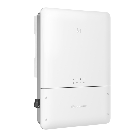
Introduction Introduction Product Introductions Introducción al producto Parts Introduction Introducción a las piezas Button For Ezlink DC Switch Wiring Conduit Hole Reset WiFi / BT Antenna WiFi Module Port 4G Antenna Terminal Terminal Mounting Bracket Heat Sink Mounting Plate [1]: Optional. Dimensions Dimensiones... - Page 10 Inverter Installation Instalación del inversor Packing List Lista de embalaje N = Quantity depends on the inverter model. Space Requirements Requisitos de espacio Children No Touch...
- Page 11 Angle Requirements Requisitos de inclinación Installing the Inverter Instalación del inversor...
- Page 12 Electrical Connection Conexión eléctrica Removing the Cover Extracción de la cubierta...
- Page 13 Cable Specifications Especificaciones de los cables Terminal/Port Silkscreen Recommended Cable Specifications PV1+ PV1- PV2+ PV2- PV3+ PV3- (Only for PV input terminal 90℃(194°F) copper cables, 12AWG. GW7700-MS-US30, GW9600-MS-US30, GW11K4-MS-US30) Dry contact communication DRY-OUT terminal CT communication terminal Outdoors communication cables that meet Remote Shutdown DRM0 UL2919, CM/CMG(NEC type), or CMH(CSA type)
- Page 14 DC Cable Cable de CC 20mm(0.79in) 20mm(0.79in) AC Cable Cable de CA 28mm(1.10in) 28mm(1.10in) 28mm(1.10in)
- Page 15 Communication Connection Conexión de comunicación Function Definition COM/DRM0 Remote shutdown REFGEN 12V-AC_SPS power supply for RSD module RSD-12V Meter+ Meter- Meter 12V+ RS485-A RS485-B parallel connection RS485-A RS485-B...
- Page 16 The cables for remote shutdown, smart meter, parallel connection, and power supply for RSD module are connected in the same way. The following illustration shows an example of connecting smart meter communication cable. 6-8mm(0.24-0.31in) 6-8mm(0.24-0.31in) WiFi Kit (Optional) Kit de WiFi (opcional)
-
Page 17: Power On And Off
Antenna(Optional) Antena (opcional) The 4G, WiFi, and bluetooth antenna are connected in the same way. The following illustration shows an example of installing the 4G antenna. Power On and Off Encendido y apagado de la alimentación DC Isolator (Optional) Inverter AC Breaker Grid (Optional) - Page 18 Monitoring via SEMS Portal App Supervisión mediante la aplicación SEMS Portal play SEMS Portal App Store SEMS Portal APP For more detailed instructions, scan the QR codes below. MS Series 5.0-11.4kW WiFi Quick SolarGo App SEMS Portal G3(US) Installation Guide User Manual User Manual...
- Page 19 Offical Website GoodWe Technologies Co., Ltd. No. 90 Zijin Rd., New District, Suzhou, 215011, China www.goodwe.com 340-00891-00 service@goodwe.com Local Contacts...
Need help?
Do you have a question about the MS Series and is the answer not in the manual?
Questions and answers