Table of Contents
Advertisement
Quick Links
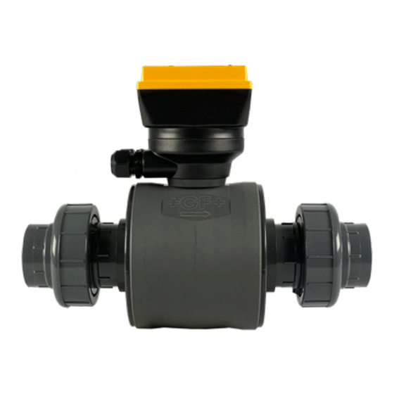
GF 2581 FlowtraMag
*3-2581.090*
3-2581.090
Rev 7 09/23
DN25
(1 in.)
DN50
(2 in.)
English
•
•
Deutsch
•
Français
•
Español
•
中文
APPROVED
Meter
®
Description
The GF 2581 FlowtraMag is a full-bore plastic PVC in-line style magnetic flowmeter. The
PVC body with Titanium or Hastelloy
three times lighter in weight compared to traditional metal magmeters on the market. It is
designed for high accuracy flow measurement in short pipe runs, making it an ideal solution
for industrial applications where performance and ease of use are important.
The FlowtraMag is available in pipe sizes of DN25 (1 in.), DN40 (1.5 in.), DN50 (2 in.),
DN80 (3 in.) and DN100 (4 in.), optimized for performance in short pipe runs often
associated with final effluent lines, well heads and water treatment skids.
DN40
Features include:
(1.5 in.)
•
No moving parts
•
No pressure drop
•
Lighter in weight compared to traditional metal magmeters
•
Reduced straight run requirements, ideal for final effluent lines, well heads and skids
•
Factory calibrated with certificate (±1% of reading accuracy)
•
Partially filled pipe detection status indicator
•
Visual LED indicators make sensor status clear and easy to read
•
Reverse flow direction configurable with 0252 Configuration Tool or GF Config Tool
Bluetooth
•
One device with three different outputs: field selectable Frequency or Digital (S³L),
and analog 4 to 20 mA, in both passive and active configuration
•
On-the-fly configuration with GF Config Tool Bluetooth
•
Bluetooth
instantaneous flow reading
DN 80
(3 in.)
Table of Contents
Warranty Information ...............................................................................2
Safety Information ...................................................................................2
Chemical Compatibility ............................................................................2
Temperature-Pressure Graph ..................................................................2
Specifications ..........................................................................................3
Sensor Dimensions .................................................................................4
Sensor Location.......................................................................................5
Selecting a Location ................................................................................5
Sensor Mounting Angle ...........................................................................5
Sensor Pipe Installation ...........................................................................6
Wiring Configuration ................................................................................8
Default Configurations .............................................................................9
Wiring ....................................................................................................10
EMI Filter Wiring ....................................................................................12
App Configuration - Setup .....................................................................13
App Configuration - Monitor and Real Time Log ...................................15
App Configuration - Files .......................................................................16
App Configuration - Sensor Setup .........................................................16
Calibration .............................................................................................18
C
US
Customization and Performance Settings .............................................18
E171559
Averaging and Sensitivity Settings ........................................................19
Grounding ..............................................................................................20
LED Status Indicators ............................................................................20
Configuration - 0252 Configuration Tool ................................................21
Troubleshooting .....................................................................................24
Ordering Information..............................................................................27
Patent #: US 10,712,184 B1
Other U.S. and International Patents Pending
Operating Instructions
C electrodes has no moving parts and is two to
®
App
®
4.2 capable, support iOS and Android for simple user configuration with
®
English
App
®
Advertisement
Table of Contents

Related Manuals for GF FlowtraMag 2581


Summary of Contents for GF FlowtraMag 2581
-
Page 1: Table Of Contents
3-2581.090 Rev 7 09/23 Operating Instructions Description The GF 2581 FlowtraMag is a full-bore plastic PVC in-line style magnetic flowmeter. The PVC body with Titanium or Hastelloy C electrodes has no moving parts and is two to ® three times lighter in weight compared to traditional metal magmeters on the market. It is designed for high accuracy flow measurement in short pipe runs, making it an ideal solution for industrial applications where performance and ease of use are important. -
Page 2: Warranty Information
However, if the plastic encloses other sensitive standards or other solutions) are warranted out of box but not components, as is the case with GF FlowtraMag meter, these warranted against any damage, due to process or application may be affected or damaged by the media diffusing through the failures (e.g. -
Page 3: Dn100 (4 In.)
(0.14 to 70.36 GPM) Low Energy (BLE) 4.2 Specification DN40 (1.5 in.) ......1.36 to 662.34 LPM GF Config Tool App available in iOS and Android (0.36 to 174.97 GPM) App Stores DN50 (2 in.) ......2.23 to 1112.60 LPM (0.59 to 293.92 GPM) -
Page 4: Sensor Dimensions
Sensor Dimensions WARNING: ASTM and Metric pipe cutout dimensions are different. DN25, 1 in. DN80, 3 in. Metric and ASTM union ends and union nuts shown. Flange bolt kits and gaskets not shown (Sold separately). 99.2 mm 99.2 mm (3.91 in.) (3.91 in.) 327.6 mm 249.4 mm... -
Page 5: Sensor Location
ENTER Sensor Mounting Angle Horizontal Pipe Runs DO NOT HANDLE BY THE SENSOR HEAD! GF recommends installing the sensor electronics at the Always handle FlowtraMag Meters by the union nuts 12 o'clock position. or flanges, NOT the sensor head. 2581 FlowtraMag Meter ®... -
Page 6: Sensor Pipe Installation
2 x 90° Elbow Sensor Mounting Angle Continued Pump/Valve 3 dimensions Vertical Pipe Runs To ensure pipe is flowing full with some back pressure, it is highly recommended that the fluid flows upward. 3 x I.D. 2 x I.D. 3 x I.D. 2 x I.D. - Page 7 Sensor Pipe Installation Tighten bolts by first assembling and hand tightening the nuts 2581 FlowtraMag DN80 (3 in.) to position the gasket in place. Then tighten the bolts in a 2581 FlowtraMag DN100 (4 in.) diagonal pattern 50% the recommended torque, then 100% of recommended torque.
-
Page 8: Wiring Configuration
Brown 4 to 20 mA Black Shield Blue used for GF Config App password reset only Electromagnetic Compatibility (EMC) Recommendations Complex instrumentation systems such as the 2581 FlowtraMag and the associated devices may face challenges involving Electromagnetic Interference (EMI) that present as erratic readings. -
Page 9: Default Configurations
Application Tip: Recommended: If your flow is in the reverse direction, it is possible to set up reverse flow via the GF 0252 Configuration Tool or GF The directional arrow should be pointed Config Tool App. DOWNSTREAM for correct operation. If the 2581 FlowtraMag is installed on a vertical pipe, the cable ports should be turned to point downward. -
Page 10: Wiring
Choose Passive or Active Blue not used in Bluetooth App White Not used Shield Wiring with Frequency Output Compatible with all POWERED GF Flow Instruments • When choosing Frequency in the 2581 Bluetooth App, the 2581 FlowtraMag ® Black –... - Page 11 Blue not used Terminal Brown Black Not used Shield 9900 9900 Power Transmitter Input 2581 PWR+ Black PWR– Power cable LOOP+ LOOP– – 24 VDC @ 1A min. Power Supply GF Config Tool App set to S 2581 FlowtraMag Meter ®...
-
Page 12: Emi Filter Wiring
Wiring with Digital (S L) Output Continued 2581 FlowtraMag Wiring to GF 9950 9950 9950 Digital (S Frequency GF Config Tool App set to S DC POWER DC POWER PWR+ PWR+ PWR– PWR– Loop1+ Loop1+ Loop1– Loop1– Loop2+ Loop2+ Loop2–... -
Page 13: App Configuration - Setup
Search for GF Configuration Tool in the App store. Download the GF Config Tool. Press GET. App will install on phone or other wireless device. Return to home screen and look for App icon, click the blue GF Config Tool icon Continue to Sensor Setup Section (next page) Config Tool... - Page 14 (example shows Menu) Note: If the GF Config Tool password has been lost or forgotten, connect blue wire to white wire while unit is powered (for 2 to 5 seconds.) Password will reset to factory original (last 6 digits of serial number.)
-
Page 15: App Configuration - Monitor And Real Time Log
App Configuration - Monitor and Real Time Log Monitoring flow and totalizer Live Logging while connected to mobile / tablet device, set 1 sec or more increments iOS version Note: The logging screen only logs current screen view in real-time when connected to the app. -
Page 16: App Configuration - Files
NOTE: This will overwrite any changes made in the GF Config Tool App since the last Write. Write Applies the data entered in the GF Config Tool App to the connected device. Once you have entered the desired setting changes in the software screens, press Write to load your new settings onto the connected device. - Page 17 To switch between digital (S L) and Frequency and/or 4 to 20 Calibration Active or Passive, use the GF Config Tool App. On the loop Custom Calibration of screen, use the drop down to select digital (S L) or Freq Rate, Volumetric, Zero and/or Active or Passive 4 to 20 mA.
-
Page 18: Calibration
1151.200 Customization and Performance Settings For customization and performance settings, use the GF Config Tool App or the GF 0252 Configuration Tool and software. Refer to the GF 0252 Configuration Tool manual for details to adjust the following parameters: ³... -
Page 19: Averaging And Sensitivity Settings
Averaging and Sensitivity Settings • Because ideal flow conditions are often impossible to achieve, the fluids flow is often erratic, which causes erratic readings in control features (e.g., relays, 4 to 20 mA loops, etc.) that are associated with the flow rate. •... -
Page 20: Grounding
Grounding Inconsistent or inaccurate readings can occur due to electrical noise radiated through the fluid when the fluid has very high conductivity or noise levels. In these cases, it is strongly recommended to install grounding rings or metallic couplings immediately upstream and downstream of the 2581 FlowtraMag and connect them to an isolated earth ground wire (12 AWG/4mm^2 wire recommended). -
Page 21: Configuration - 0252 Configuration Tool
Configuration - 0252 Tool This is an outline. For complete instructions, please refer to the 0252 Configuration Tool manual. Select default unit by type, then click ok. Then click on Read from the device. The Application tab, select flow unit (drop down menu), totalizer unit (drop down menu), Averaging (drop down... - Page 22 Configuration - 0252 Tool The Loop tab select or confirm your 4 to 20 mA set point, set your current alarm condition and type of output mode. If the user has any correction or change, you must Write the information to device, then click Read device again.
- Page 23 Configuration - 0252 Tool The Monitor tab can graph or log the information to your local drive via file type with the extension .CSV 8. The Calibration tab allows custom calibration via method of rate, volumetric, zero flow calibration and reset flow calibration.
-
Page 24: Troubleshooting
If problem persists, use grounding rings. Contact technical support. Frequency Bluetooth selection is S Select frequency from GF Config Tool or output does not Improper wiring. 0252 Configuration Tool. work Check wiring. Use the wiring diagram picture in the 2581 FlowtraMag manual. - Page 25 (for 2 to 5 seconds.) Password will reset to factory original (last 6 digits of serial number.) Measurement Improper calibration. 1. Use the GF Config Tool App or 0252 inaccurate Sensor fault as indicated by the Configuration Tool to reset flow and/or zero Red LED.
- Page 26 Notes 2581 FlowtraMag Meter ®...
-
Page 27: Ordering Information
Ordering Information Mfr. Part No. Code Description 3-2581-PT01-101 159 001 970 FlowtraMag, PVC, Titanium, FKM O-Ring, Union, DN25 (1 in.) 3-2581-PT15-101 159 001 971 FlowtraMag, PVC, Titanium, FKM O-Ring, Union, DN40 (1.5 in.) 3-2581-PT02-101 159 001 972 FlowtraMag, PVC, Titanium, FKM O-Ring, Union, DN50 (2 in.) 3-2581-PT03-101 159 001 973 FlowtraMag, PVC, Titanium, FKM O-Ring, Flange, DN80 (3 in.) - Page 28 Ordering Information Accessories Mfr. Part No. Code Description 3-0252 159 001 808 0252 Configuration Tool (optional for configuring with PC) 3-2581.391 159 002 143 2581 FlowtraMag EMI Filter Kit 5523-0222 159 000 392 Cable (per foot), 2 cond. w/shield, 22 AWG 5523-0224 159 855 034 Cable (per foot), 6 cond.
Need help?
Do you have a question about the FlowtraMag 2581 and is the answer not in the manual?
Questions and answers