Advertisement
Signet 5090 Flow Monitor
*3-5090.090-1*
3-5090.090-1
Rev. K 08/13
1. Compatible Sensor Wiring
5090 Rear
Terminal
Connection
Sensor
Input
Technical Notes:
•
Remove terminal block for easy wiring (Fig. 1)
•
Maintain cable shield through cable splice.
•
Route sensor cable away from AC power lines.
•
Use 2-conductor shielded cable for sensor cable extension up
to 61 m (200 ft).
2. Calibration
The 5090/515 fl ow metering system utilizes the AC signal
amplitude from the 515 sensor to drive the 5090 meter.
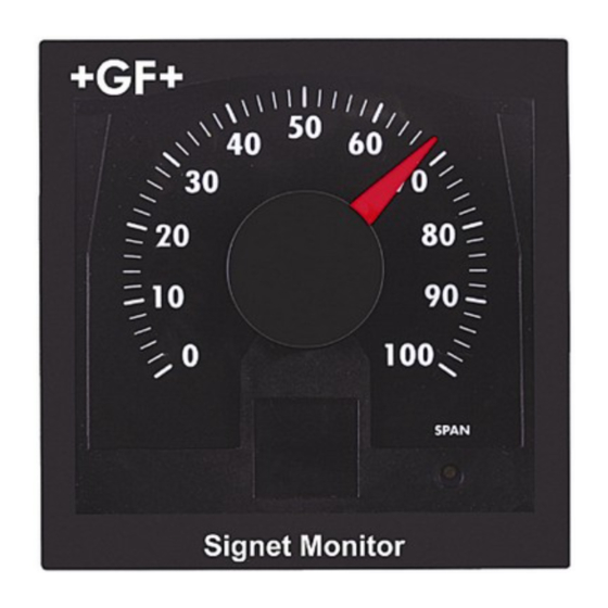
The front panel meter movement adjustment (SPAN) is easily
accessed under the removable front window for simple calibration.
A dial kit with six dial ranges, assorted fl ow unit/multiplier decals,
and dial installation instructions is included for your convenience.
Equipment Required
•
Frequency counter
•
Signet 515 Sensor installed in process line
•
Standard and phillips head screwdriver
Procedure
1. Induce the maximum (stable) fl ow rate in your process line.
2. Using the frequency counter, monitor and record the 515
sensor frequency output:
Sensor Frequency = ___________________________ Hz
Technical note:
Sensor frequency MUST be greater than 45 Hz for full scale
needle defl ection.
3. Calculate the actual max. fl ow rate in your process line as follows:
Maximum fl ow rate = Sensor frequency (step 2) × A-Factor (Section 6)
Maximum Flow Rate = __________________________________
515
Silver (shield)
Black (AC signal out)
Red (AC signal out)
Red
Frequency
counter
Black
5 6
4
3
7
2
8
1
9
0
10
GPM
SPAN
X100
Signet Monitor
Sensor
Sensor
Input
Input
515 Circuit
Red
Black
Rotor
Shield
w/magnets
4. Install the appropriate dial face and fl ow unit/multiplier decal
for the maximum fl ow rate (Step 3). Refer to dial installation
instructions included with dial kit.
The dial kit includes the following:
Assorted Unit and Multiplier Decals:
X 10
1
X 100
1
X 1,000
5
4
5
4
3
3
X 10,000
2
2
2
0
1
1
0
0
0
Example: A fl ow system's maximum fl ow rate is 18.3 GPM.
The proper dial and fl ow unit/multiplier decal for this fl ow system is:
0 - 2 dial + GPM × 10 decal.
5. Disconnect frequency counter.
Access and adjust the "SPAN" potentiometer to match the
calculated maximum fl ow rate from Step 3.
After adjustment, calibration is complete.
U L
LISTED
77CJ
Fig. 1
5090
5
4
6
3
7
SPAN
2
8
1
9
10
0
GPM
SPAN
X 100
Signet Monitor
6 Dials:
0-2
0-4
0-6
0-8
6
6
3
m
/h
7
7
0-10
GPM
8
8
x 10
LPM
0-100
9
x 1,000
2
9
10
SPAN
10
SPAN
SPAN
SPAN
English
Advertisement
Table of Contents

Subscribe to Our Youtube Channel
Related Manuals for GF Signet 5090


Summary of Contents for GF Signet 5090
- Page 1 Signet 5090 Flow Monitor English *3-5090.090-1* 3-5090.090-1 Rev. K 08/13 1. Compatible Sensor Wiring 5090 Rear Terminal LISTED Connection 77CJ Sensor Sensor Sensor Input Input Input Silver (shield) Black (AC signal out) Red (AC signal out) Technical Notes: • Remove terminal block for easy wiring (Fig. 1) •...
- Page 2 Parts and Accessories 5 x 5 inch adapter plate for There are no user replaceable components in the 5090. retrofi tting Signet 500 series Unauthorized repair attempts may void warranty. 3-5000.399 (code 198 840 224) • Front snap-on bezel, 3-5000.525 (code 198 840 226) •...
- Page 3 4 IN. IR8S040 8.7591 33.1533 1.9892 5 IN. IR8S050 11.2570 42.6079 2.5565 6 IN. IR8S060 15.9574 60.3989 3.6239 8 IN. IR8S080 28.1690 106.6197 6.3972 10 IN. IR8S100 44.4444 168.2222 10.0933 12 IN. IR8S120 62.5000 236.5625 14.1938 Signet 5090 Flow Monitor...
- Page 4 A-Factors for DIN Pipes ------------------------------ A-FACTORS ------------------------------- ---------------------------------- 1 Hz = ------------------------------------ PIPE SIGNET SIZE FITTING U.S. GPM m3/h CODE POLYPROPYLENE FITTINGS (DIN/ISO AND BS AND ANSI) DN 15 PPMT005 0.1246 0.4716 0.0283 727 310 036 DN 20 PPMT007 0.2165 0.8196 0.0492 727 310 037...
Need help?
Do you have a question about the Signet 5090 and is the answer not in the manual?
Questions and answers