Table of Contents
Advertisement
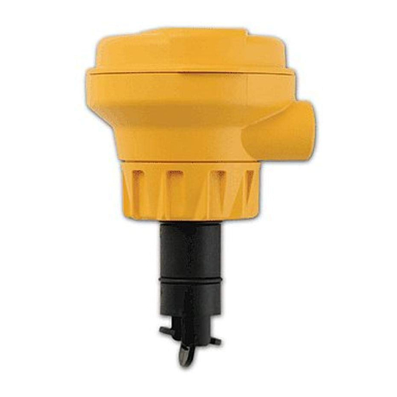
Signet 2537 Paddlewheel Flowmeter
*3-2537.090*
3-2537.090
Rev G 9/12
SAFETY INSTRUCTIONS
1.
Depressurize and vent system prior to installation or removal.
2.
Con¿ rm chemical compatibility before use.
3.
Do not exceed maximum temperature/pressure speci¿ cations.
4.
Wear safety goggles or faceshield during installation/service.
5.
Do not alter product construction.
6.
If this equipment is used in a manner not speci¿ ed by the manufacturer, the protection provided
by the equipment may be impaired.
7.
This device is not approved for use or installation in hazardous locations.
Description
The 2537 Paddlewheel Flowmeter Series offer low À ow, low power and high resolution with various output options such as a Volumetric
Pulse, Pulse Divider, Flow Switch, Digital (S
interface.
• The 4 to 20 mA model provides a blind current loop output.
• The Digital (S
L) model provides a Digital (S
3
• The Multi model uses a single relay (mechanical or solid state) and has three selectable operating modes:
• Divider Mode scales the paddlewheel frequency down to accommodate low frequency input devices.
• Total Mode outputs one pulse per a set volume of À uid.
• Flow Switch Mode uses a single relay for Hi or Lo alarm operation.
A small LCD enables the 2537 to be programmed without any external equipment. During normal operation the display is not visible.
For earlier versions of this sensor, please visit our manual archives at www.gfsignet.com and download the 2537 rev C manual.
Specifi cations
General
Wetted Materials
Model Suffi x
Sensor Body
-P0, -P1
glass-¿ lled PP
-T0
PVDF, Natural
Case:
PBT, yellow
Inside Cover:
Valox, black
Wiring Ports:
½ in. NPT threads; liquid-tight
connector accepts cables 7 to
10 mm OD (0.275 in. to 0.394 in.)
Power Requirements
Multi:
with Dry-Contact Relay:
24 VDC nominal, ±10%, regulated
30 mA max. current
with Solid-State Relay:
5 to 24 VDC nominal, ±10%, regulated
30 mA max. current
Digital (S
L):
5.0 VDC min. to 6.5 VDC max.
3
30 mA max. current (1.5 mA nominal)
4 to 20 mA:
400 mV max. ripple voltage
30 mA max. current
Reverse Polarity and Short Circuit Protected: Up to 40 V, 1 hour
Over-Voltage Protection:
> 40 VDC over 1 hour
English
L), or 4 to 20 mA. This unit can be con¿ gured on-site directly through the built-in user
3
L) output for use with the Signet 8900 Multi-Parameter Controller or 9900 Transmitter.
3
Rotor
Pin
PVDF, Black;
Titanium
optional ETFE
w/ or w/o carbon
¿ ber reinforced
PTFE sleeve
PVDF, Natural;
PVDF,
optional ETFE
Natural
w/ or w/o carbon
¿ ber reinforced
PTFE sleeve
Paddlewheel Sensor Performance Specifi cations
Pipe Size Range:
Min. Reynolds Number:
Paddlewheel Frequency: 49 Hz per m/s nominal
O-ring
FPM
Operating Range:
Linearity:
Repeatability:
Electronics Performance Specifi cations
Input Frequency Range:
FPM
System Response:
Environmental Requirements
Enclosure Rating:
Storage Temperature:
Ambient Temperature:
Relative Humidity:
Altitude:
Pollution Degree:
Output Specifi cations
Signal Averaging:
Sensitivity Response:
Pulse Divider/Total Pulse Output
Pulse Divider Setting:
DN15 to DN200 (½ in. to 8 in.)
4500
(15 Hz per ft/s nominal)
0.1 m/s to 6 m/s (0.3 ft/s to 20 ft/s)
±1% of max. range @ 25 °C (77 °F)
±0.5% of max. range @ 25 °C (77 °F)
1 to 1000 Hz
100 ms update rate nominal
NEMA 4X/IP65
-10 to 75 °C (14 to 167 °F)
0 to 65 °C (32 to 150 °F)
0 to 90% RH, non-condensing
2000 m (6,562 ft)
2
Programmable 0 to 100 seconds
Programmable 0 to 9 scale
1.0000 to 99999
Maximum pulse rate: 300 Hz
Maximum pulse width: 50 ms
English
Advertisement
Table of Contents

Related Manuals for GF Signet 2537


Summary of Contents for GF Signet 2537
- Page 1 Signet 2537 Paddlewheel Flowmeter English *3-2537.090* 3-2537.090 Rev G 9/12 English SAFETY INSTRUCTIONS Depressurize and vent system prior to installation or removal. Con¿ rm chemical compatibility before use. Do not exceed maximum temperature/pressure speci¿ cations. Wear safety goggles or faceshield during installation/service.
-
Page 2: Chemical Compatibility
If the plastic material is compatible with the medium according to the application guidelines, the permeation will not damage the plastic itself. However, if the plastic encloses other sensitive components, as is the case with GF Signet plastic paddlewheel sensors, these may be affected or damaged by the media diffusing through the plastic body and rotor. -
Page 3: Location Of Fitting
Over 4 inch, cut 2-1/8 inch hole in pipe For pipes from DN 15 to 50 mm Union saddles Special order 14 in. to 36 in. PP or PVDF Fitting Metric For pipes DN65 to 200 mm Wafer Fitting PP or PVDF Signet 2537 Flowmeter... -
Page 4: Installation
S 3 L S L (Red) Input GND (White/Shield) +5VDC (Black) S 3 L S L (Red) Input GND (White/Shield) Analog Output 1 Connection to Connection to (if applicable) 9900 Transmitter Analog Output 2 8900 Controller (if applicable) Signet 2537 Flowmeter... - Page 5 Blk Red Shld Blk Red Shld 10KΩ Relay Rating: 3-2505.616A Solid-State Dry-Contact 5A @ 250VAC – Relay Relay 5A @ 30VDC Relay Rating: Power Supply 100mA @ 40VDC Load 5 to 24 VDC, 70mA @ 33VAC 0.03 A Signet 2537 Flowmeter...
-
Page 6: Operation
• If the white key (S1) is held down for three seconds, the À ow rate is displayed for 10 minutes before reverting back to the model name. • In the Multi Model, if the “Multi” menu item is set to “divider”, then the divided pulse output will be displayed in pulses/seconds (p/s). Signet 2537 Flowmeter... -
Page 7: Menu Details
Set À ow RATE to be represented by 4 mA 0.0000 to 99999 page 8 20 Set Set À ow RATE to be represented by 20 mA 0.0000 to 99999 page 8 Contrast Adjust visibility of liquid crystal display 1 to 3 page 8 Signet 2537 Flowmeter... -
Page 8: Flow Units
The factory setting of 3 is the highest contrast setting. Choose: Save the new setting: Save the new setting: Return to Normal Operation Go to next menu item Return to Normal Operation Go to next menu item Signet 2537 Flowmeter... -
Page 9: Set Averaging
Set the Averaging for 50 seconds. Example: Set the Sensitivity to 5. Save the new setting: Save the new setting: Return to Return to Normal Operation Normal Operation Go to next Go to next menu item menu item Signet 2537 Flowmeter... - Page 10 P-Factor = 2 (gallons out per pulse) 1 Gal 2 Gal 3 Gal 4 Gal Pulses IN Pulses OUT Return to Normal Operation Go to next menu item Save the new setting: Return to Normal Operation Go to next menu item Signet 2537 Flowmeter...
- Page 11 When the À ow rate reaches the setpoint, the 2537 will wait this long (in seconds) before triggering the alarm. The factory setting is 0000.0 seconds. Minimum value Maximum value Return to Normal Operation Go to next menu item Signet 2537 Flowmeter...
- Page 12 176.44 46.615 1-1/2 CUKT015 115.69 30.565 CUKT020 63.385 16.746 COPPER TEE FITTINGS ON COPPER PIPE SCH L CUKT005 858.22 226.74 CUKT007 385.74 101.91 CUKT010 241.64 63.841 1-1/4 CUKT012 170.90 45.152 1-1/2 CUKT015 112.03 29.598 CUKT020 61.74 16.310 Signet 2537 Flowmeter...
- Page 13 DN150 7.3119 1.9318 PPMTF060 PPMTE080 DN200 3.9946 1.0554 PPMTF080 PVDF WAFER FITTINGS (DIN/ISO) DN65 SFMTF025 36.133 9.5465 DN80 SFMTF030 24.715 6.5297 DN100 SFMTF040 16.120 4.2589 DN125 SFMTF050 8.8624 2.3415 DN150 SFMTF060 6.4543 1.7052 DN200 SFMTF080 4.0720 1.0758 Signet 2537 Flowmeter...
-
Page 14: Maintenance And Cleaning
DO NOT À ex the ear any more than necessary! If it breaks, the sensor cannot be repaired. 3. Install the new rotor by inserting one tip of the pin into the hole, then carefully À ex the opposite ear back enough to slip rotor into place. Signet 2537 Flowmeter... - Page 15 Notes Signet 2537 Flowmeter...
-
Page 16: Ordering Information
Ordering Information Mfr. Part No. Code Description 2537 system for 0.5 in. to 4 in. pipes, with polypropylene body, Black PVDF rotor, Titanium pin, FPM O-rings 3-2537-1C-P0 159 001 291 Pulse/Flow Switch, DCR, -P0, Integral Mount 3-2537-2C-P0 159 001 292 Pulse/Flow Switch, SSR, -P0, Integral Mount 3-2537-5C-P0 159 001 295...
Need help?
Do you have a question about the Signet 2537 and is the answer not in the manual?
Questions and answers