Table of Contents
Advertisement
Advertisement
Table of Contents

Related Manuals for GF U1000 V2


Summary of Contents for GF U1000 V2
- Page 1 GF Piping Systems User Manual U1000 V2 Ultrasonic Flowmeter...
-
Page 2: Table Of Contents
Scope of delivery ....................... 9 Installation ........................9 Positioning the transducers ..................... 9 Preparation ........................10 Start-Up..........................10 Adjusting the sensor distance ..................12 Mounting the U1000 V2 on the pipe ................14 8.5.1 Selecting the pipe adapter ....................14 8.5.2 Apply sound-conductive paste ..................15 8.5.3 Mounting the guide rail ....................15... - Page 3 Intended use Instruction manual 8.8.1 Interface cable .........................17 8.8.2 Pulse output ........................18 8.8.3 4-20 mA Output ........................18 Modbus option .........................18 8.9.1 Interface cable .........................18 8.9.2 Modbus connections ......................19 Operation ..........................19 Entering the pipe inside diameter ..................19 Setting the pulse output ....................21 Current output 4 - 20 mA ....................21 Modbus ..........................21 Switching off and on again ....................23...
-
Page 4: Intended Use
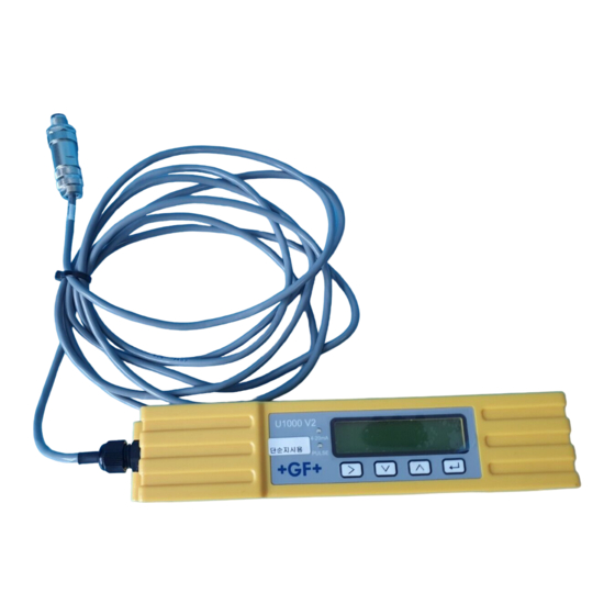
Instruction manual Intended use Intended use The U1000 V2 ultrasound flowmeter is used to obtain an optimal measurement of the volume flow and flow rate in steel and plastic pipes with outside diameter from 22 mm (0.86”) to 180 mm (7”). -
Page 5: Other Related Documents
Listing of items on various levels • 2.2 Other related documents Georg Fischer industrial planning fundamentals These documents are available through agents of GF Piping Systems or at www.gfps.com. 2.3 Abbreviations Abbreviation Description Acrylonitrile-butadiene-styrene Double acting function Electromagnetic Compatibility... -
Page 6: Transport And Storage
Electronics module Pipe The U1000 V2 consists of an electronics module (3) and a guide rail (4), which together form a single unit which is fixed to the pipe (6) by pipe clamps (2). The U1000 V2 is supplied with power through an external 12 – 24 V power adapter (1). -
Page 7: User Interface
Design and function Instruction manual Principle of operation A periodic voltage pulse acts on the transducer crystals and produces an ultrasound beam at a certain frequency. The beam is first transmitted by the downstream transducer (blue) to the upstream transducer (red). The beam is then sent in the opposite direction, i.e. -
Page 8: Technical Specifications
Instruction manual Technical specifications Technical specifications Data Kv value Measurement technology Transmission time Measurement channels Resolution of time calculation ± 50 ps Dynamics (turn-down ratio) 200:1 Flow rate 0.1m/s - 10m/s (0.3 ft/s - 32 ft/s) Usable liquid types High purity water, clean water with < 3 percent by volume of particle content, or up to 30% ethylene glycol. -
Page 9: Default Values
Technical specifications Instruction manual Data Kv value Material Polycarbonate Mounting Pipe mountable Protection class IP54 Fire classification UL94 V-0 Dimensions 250 mm x 48 mm x 90 mm (electronics + guide rail) Weight 0.5 kg Ambient conditions Pipe temperature 0 °C to +85 °C Operating temperature 0 °C to +50 °C (electronics) -
Page 10: Scope Of Delivery
Installation 8.1 Positioning the transducers The U1000 V2 requires an even and uniform flow profile, since distortions in the flow can cause unpredictable measurement errors. In many applications, however, it is not possible to have a uniform flow rate through 360°. -
Page 11: Preparation
T-branches, valves, pumps and similar obstacles. To ensure that the U1000 V2 is positioned at a place that has an undistorted flow profile, the transducers must be mounted sufficiently far from possible sources of distortion to prevent these from having any effect on the measurement. - Page 12 Instruction manual Installation The U1000 V2 boots for the first time. The GF start screen is displayed for 5 s. The start-up wizard automatically starts. Enter pipe id menu appears. Select your pipe inside diameter and press to acknowledge.
-
Page 13: Adjusting The Sensor Distance
Define optimal sensor distance with entering your pipe credentials in the U1000 V2 start- up wizard (see section 8.3 Start-Up). (E.g. B-4 for PVC-U pipe with 50 mm inside diameter) - Page 14 Instruction manual Installation Move the sensors to the optimal position (see start-up wizard in section 8.3 Start-Up). Tighten the sensor mounting screws. NOTICE NOTE. When the sensors have been moved to the correct setting and the guide rail is attached to the pipe REMOVE the sensor holding screws, which will allow the spring loaded transducers to make contact with the pipe.
-
Page 15: Mounting The U1000 V2 On The Pipe
Installation Instruction manual 8.5 Mounting the U1000 V2 on the pipe 8.5.1 Selecting the pipe adapter Two adapters are available for attaching the measuring device to pipes with an outside diameter of ≤ 60 mm. NOTICE If these adapters are not necessary, store them away for a possible later change of position. -
Page 16: Apply Sound-Conductive Paste
Instruction manual Installation 8.5.2 Apply sound-conductive paste Using the syringe, apply sound-conductive paste (3) to the sensor contact surfaces (1) and (2). 8.5.3 Mounting the guide rail Mount the guide rail (1) and pipe adapters if necessary (see section 8.5.1 Selecting the pipe adapter) on the pipe (3) using the pipe clamps (2). -
Page 17: Install The Electronics Module
Installation Instruction manual 8.5.4 Install the electronics module Connect the power supply (1) to the electronics module (2). Plug the cables of the two sensors into the sockets (3) and (4) on the electronics module. The cables can be assigned as desired. ... -
Page 18: Electrical Connection Of The U1000 V2
8.7 Electrical connection of the U1000 V2 NOTICE The U1000 V2 operates in the voltage range 12 – 24 V (AC/DC). The power supply must have a minimum rating of 7 VA per instrument. To fully meet the requirements of EMC regulations, a 12 V connection is recommended for domestic and light industrial applications. -
Page 19: Pulse Output
CAUTION WARNING Electric shock due to short-current! Before connecting the U1000 V2 to an external power supply, make sure that the power supply is switched off. 8.8.2 Pulse output The isolated pulse output is provided by a SPNO/SPNC MOSFET relay which has a maximum load current of 500mA and maximum load voltage of 48V AC. -
Page 20: Modbus Connections
& Implementation guide V1.0”. Operation 9.1 Entering the pipe inside diameter Switch on the U1000 V2 for the first time. The GF start screen is displayed for 5 s. The hundreds digit (050.0) for the pipe inside diameter flashes. - Page 21 Operation Instruction manual Press and hold the button. The number sequence scrolls automatically. Press the button. The flashing tens digit (050,0) decreases through the number sequence 9, 8, 7, 6, 5, 4, 3, 2, 1, 0. Press and hold the button. The number sequence scrolls automatically.
-
Page 22: Setting The Pulse Output
Instruction manual Operation 9.2 Setting the pulse output The pulse output can be set in two different operating modes: Volume based mode After a measured volume of 10 l (preset value), a pulse is sent => 1 pulse/10 l. ... - Page 23 Operation Instruction manual Modbus Register Type Typical Meaning Notes Register Offset Contents Byte 0x01 Instrument Address Instrument Byte 0x03 Command Number of bytes Byte 0x40 to read 0x00 40001 Int-16 Device ID 0xac 0x00 0x0000 OK 40002 Int-16 Status Not[0x0000] Fault 0x00 0x00 40003...
-
Page 24: Switching Off And On Again
Instruction manual Password-protected menus 9.5 Switching off and on again If the power supply is switched off and then on again after the pipe inside diameter is entered for the first time, then the last applied configuration is used. If the configuration is changed for some reason, the password-protected menu must be used. See Section 10 Password-protected menus, Page 23. -
Page 25: Changing The Selection Menus
Password-protected menus Instruction manual Press the button User Menu: Exit. The new values are stored and the password-protected menu is closed. 10.3 Changing the selection menus NOTICE The procedure for changing the preset values is the same for all menus. ... -
Page 26: Password-Protected Menu Structure
Instruction manual Password-protected menus The hundreds digit (01000.0) flashes. Press the button twice. The flashing hundreds digit (01000.0) changes to 2. Press the button. The tens digit (01200.0) flashes. Press the button five times. The flashing tens digit (01200.0) changes to 5. ... -
Page 27: Setup
Password-protected menus Instruction manual User Menu: See Section 10.5.6 "Total", Page 30. Totals User Menu: Exit Checking Signals ***** Sig: 87% 246.3 l/min 10.5.2 Setup Metric units See Imperial units, Select Dimension: Page 28 inches mm | inches Invalid Range 20 – 110 mm Enter Pipe ID: 050.0 mm 050.0 mm... - Page 28 Instruction manual Password-protected menus Instrument Fluid: Glycol|Water Set Temperature: HOT|COLD Set Separation: See Section 10.5.1 "Overview", Page 25.
- Page 29 Password-protected menus Instruction manual Imperial units See Metric units, Select Dimension: Page 26. mm | inches Invalid inches Range 0.79 – 4.33 Enter Pipe ID: 2.000 inches 2.000 inches Valid & Valid Select Reading Flow | Vel Flow USgal System Units: Impgal | USgal impgal Flow Units:...
-
Page 30: Pulse Output
Instruction manual Password-protected menus 10.5.3 Pulse output & OFF Select Pulse: Test mode ON | OFF Press the button. A pulse is generated Pulse Type: VOLUME | FREQ Volume Freq Max Pulse Freq: Volume per Pulse 10.0 l Valid Valid Invalid Range 1 –... -
Page 31: Calibration
Password-protected menus Instruction manual 10.5.5 Calibration Damping Time [s]: Zero Cut-off: Range 0.00 – 0.50 Invalid 0.10 m/s 0.10 m/s To Set Valid Zero Offset: Zero Offset To clear Averaging…9 0.000 l/min Done Calibrat. Factor: Range 0.500 – 1.500 Invalid 1,000 1,000 Valid... -
Page 32: Diagnosis
The lower line shows its 5060-01-01-01-03 status. The software version (Rev.) and serial number Rev: 05.00.001 (S/N) of the U1000 V2. S/N:112547 06/19 The gain factor is displayed as an indication of Gain 845 (x1) signal strength and switch setting. The values DT 125 ns for a good signal 600 –... -
Page 33: Maintenance Plan
Risk of injury and loss of product quality through the use of spare parts not provided by GF Piping Systems! Risk of injury and damage to property. If repairs are necessary, please contact your national agent for GF Piping Systems. 12.1 Maintenance plan Set the maintenance intervals according to the operating conditions (e.g. ambient temperature). - Page 34 Fault type Error message Cause and remedy No BBME This message indicates a device error. Switch the U1000 V2 off then on again. If this message continues to be displayed, please contact the GF Piping Systems Service department.
-
Page 35: Modbus Error Messages
Troubleshooting Instruction manual Error messages are displayed as a number in the diagnostics menu. Contact GF Support if other messages appear. Status Byte Value Error meaning Bit#7 Bit#6 Bit#5 Bit#4 Bit#3 Bit#2 Bit#1 Bit#0 TOFM signal lost TOFM board failed... -
Page 36: Removal
Switch off the external power supply and prevent it from being switched on again. Disconnect all cable connections. Loosen the pipe clamps and remove the U1000 V2 completely from the pipe along with all connecting cables. 15 Disposal ... - Page 40 GF Piping Systems Worldwide at home Our sales companies and representatives ensure local customer support in more than 100 countries. www.gfps.com Argentina / Southern South America France Mexico / Northern Latin America Singapore Georg Fischer Central Plastics Sudamérica S.R.L. Georg Fischer SAS Georg Fischer S.A.
Need help?
Do you have a question about the U1000 V2 and is the answer not in the manual?
Questions and answers