Table of Contents
Advertisement
Quick Links
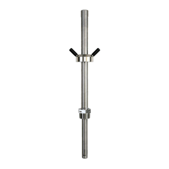
Signet 2552 Magmeter
*3-2552.090*
3-2552.090
Rev. C 04/07
SAFETY INSTRUCTIONS
1.
Depressurize and vent systems without Hot-tap valve prior to installation or removal.
2.
Confi rm chemical compatibility before use.
3.
Do not exceed maximum temperature/pressure specifi cations.
4.
Wear safety goggles or face shield during installation/service.
5.
Do not disassemble or alter product construction.
6.
Disconnect power before attempting any service or wiring.
Specifi cations
Wetted Materials:
•
316L Stainless Steel body and electrodes
•
PVDF Insulator
•
O-rings:
FPM standard, EPDM, Kalrez® optional
•
Cable: 4-cond + shield, PVC jacket (Fixed cable models)
•
Watertight rubber cable assembly w/NEMA 6P connector
(Submersible cable models)
Power Requirements
•
4 to 20 mA: 24 VDC nominal, 22.1 mA maximum
(21.6 VDC min. to 26.4 max.)
400 mV p-p maximum ripple voltage
•
Frequency: 5 to 24 VDC nominal, 15 mA maximum
(5 VDC min. to 26.4 VDC max.)
•
Digital (S
3
L): 5 VDC nominal, 15 mA maximum
(5 VDC min. to 6.5 VDC max.)
•
Reverse polarity and short circuit protected
Performance
•
Pipe size range:
•
Minimum Flow Range
Maximum Flow range:
•
Linearity:
•
Repeatability
•
Accuracy:
reference conditions where the fl uid is water at ambient
temperature, the appropriate upstream and downstream
distances are observed, the sensor is inserted at the correct
depth and there is a fully developed fl ow profi le which is in
compliance with ISO 7145-1982 (BS 1042 section 2.2))
•
Minimum Conductivity: 20 µS/cm
Output Specifi cations
Current output (4 to 20 mA)
•
Programmable and reversible
•
Loop Accuracy:
•
Temp. drift:
•
Power supply rejection: ±1 µA per V
•
Isolation: Low voltage
•
Maximum cable:
Max. Loop Resistance: 300 Ω
•
•
Error condition:
Frequency output:
•
Compatible with Signet 5075, 5500, 5600, 8550 and 8900
•
Max. Pull-up Voltage:
Short Circuit Protected: ≤30 V @ 0Ω pull-up for one hour
•
•
Reverse Polarity Protected to -40 V for 1 hour
•
Overvoltage Protected to +40 V for 1 hour
•
Minimum Current Sink: 50 mA
•
Maximum cable:
2 in. to 48 in.
0.05 m/s (0.15 ft/s)
10 m/s (33 ft/s)
±1% reading + 0.1% of max. range
±0.5% of reading @ 25°C
±2% of measured value (in
32 µA max. error
(@ 25°C @ 24 VDC)
±1 µA per °C max.
<48 VAC/DC
from electrodes and auxiliary power
300 m (1000 ft.)
22.1 mA
30 VDC
300 m (1000 ft.)
3
Digital (S
L) Output:
•
Compatible with Signet 8900
•
Serial ASCII, TTL level 9600 bps
•
Maximum cable:
Tests, Approvals & Standards
•
CE
•
EN 61326 Emissions and Immunity for Control Equipment
Immunity:
EN 61000-6-1
Emissions:
EN 55011 class B
Environmental
•
NEMA 4 / IP65 (Fixed cable models only)
•
NEMA 6P / IP68 (Submersible cable models only)
•
Storage Temperature:
•
Operating Temperature (non-icing conditions)
Ambient:
Media:
•
Max. operating pressure:20.6 bar @ 25°C (300 psi @ 77°F)
bar
psi
20.6
300
19.8
275
18.1
250
16.4
225
14.7
200
12.9
175
11.2
150
9.5
125
7.8
100
6.0
75
Safe Media Pressure
4.3
50
and
2.6
25
Temperature Range
0.9
0
-20
-10
0
10
°C
°F
5
23
41
59 71
Application dependent
(See 8900 manual)
-15°C to 70°C (5°F to 158°F)
(non-icing conditions)
-15°C to 70°C (5°F to 158°F)
-15°C to 85°C (5°F to 185°F)
20
30 40 50 60 70 80 90
95 113 131
158
185
English
100
212
Advertisement
Table of Contents

Related Manuals for GF Signet 2552


Summary of Contents for GF Signet 2552
- Page 1 Signet 2552 Magmeter English *3-2552.090* 3-2552.090 Rev. C 04/07 SAFETY INSTRUCTIONS Depressurize and vent systems without Hot-tap valve prior to installation or removal. Confi rm chemical compatibility before use. Do not exceed maximum temperature/pressure specifi cations. Wear safety goggles or face shield during installation/service.
-
Page 2: Selecting A Location
41 mm 1¼ in. NPT 1.6 in. threads Inlet Outlet Flange Reducer 90° Elbow +GF+ +GF+ +GF+ 2552-1 models 187 mm/7.38 in. Stroke length 15 x I.D. 5 x I.D. 10 x I.D. 5 x I.D. - Page 3 Standard Magmeter Installation The following items are required to properly install the Magmeter: • Not supplied: • Supplied with 2552 Magmeter: • Female pipe fi tting (weld-on or saddle) • 12-inch Ruler with 1¼ in. NPT or ISO 7/1-Rc 1¼ threads •...
- Page 4 Hot-tap Magmeter Installation The following items are required to properly install the Magmeter through a Hot-tap valve: • Not supplied: • Supplied with 2552 Magmeter: • Female pipe fi tting (weld-on or saddle) • 12-inch Ruler with 1¼ in. NPT or ISO 7/1-Rc 1¼ threads •...
-
Page 5: General Installation And Grounding Tips
General Installation and Grounding Tips Sensor conditioning The Magmeter output signal may be unstable immediately after installation. Allowing the sensor to soak in a full pipe (or in any container of water) for 24 hours will stabilize the performance. • Very low conductivity fl... - Page 6 Wiring the 3-2552 with Frequency or Digital (S L) output Wiring: Frequency output (Compatible with all POWERED Signet Flow instruments.) • The 2552 outputs an open collector frequency signal that can be connected to any powered Signet fl ow 8900 Multi-Parameter Controller meter.
- Page 7 Custom System Span and Setup • The 3-0232 Setup tool enables the user to confi gure the 2552 Magmeter to suit the application. • The Setup tool connects the 2552 to a computer by converting the serial data output into standard RS232 format. •...
- Page 8 Using the 3-0232 i-Go S L to RS232 Converter and Setup Tool to customize the 3-2552 Magmeter Procedure: Set the general information about the pipe and application preferences in the Application Settings fi elds. Note: Press the "Restore Factory Settings" button while all fi elds are blank to load the setup program with factory settings. After a value is entered into any fi...
- Page 9 2552 Magmeter Averaging and Sensitivity Settings Because ideal fl ow conditions are often impossible to achieve, the fl ow rate is often erratic, which causes any control features (ie; relays, 4-20 mA loops, etc.) that are associated with the fl ow rate to also be erratic. The best solution to these problems is to correct the piping defi...
- Page 10 Calibration Data: K-factors and Full Scale Current Values The data in this table is based on dimensions of metal pipe per ANSI 36.10 and ANSI 36.19. Stainless steel and carbon steel pipe schedules are the same according to ANSI standards. /32 inch /32 inch 2.375...
- Page 11 /32 inch /32 inch 0.38 25.25 151.89 202.69 0.310 1.172 96917 25606 20/XHY 0.50 25.00 5 28/32 149.35 7 28/32 200.15 0.316 1.195 95008 25101 0.38 27.25 5 25/32 146.81 7 25/32 197.61 0.266 1.006 112879 29823 20/XHY 0.50 27.00 5 22/32 144.27 7 22/32...
-
Page 12: Maintenance
Maintenance There are no user-serviceable components in the Magmeter. • If the fl uid contains deposits and solids that may coat the electrodes, a regular cleaning schedule is recommended. • Do not use abrasive materials on the metal electrodes. Clean with soft cloth and mild detergent only. •... - Page 13 Notes 2552 Magmeter...
- Page 14 Notes 2552 Magmeter...
- Page 15 Notes 2552 Magmeter...
-
Page 16: Ordering Information
Ordering Information Model 2552 Metal Magmeter Ordering Matrix 3-2552 Mounting Depth Options - Choose One* Sensor protrusion depth = 7.3 inches Sensor protrusion depth = 9.3 inches Process Connection Options - Choose One 1¼ inch NPT Process Connection Threads 1¼ inch ISO Process Connection Threads Cable and Connector Options - Choose One Fixed Cable, 7.6 m (25 ft);...
Need help?
Do you have a question about the Signet 2552 and is the answer not in the manual?
Questions and answers