Table of Contents
Advertisement
Advertisement
Table of Contents

Subscribe to Our Youtube Channel
Related Manuals for GF CMD


Summary of Contents for GF CMD
- Page 1 User manual v1.8...
-
Page 3: Table Of Contents
Input of Numerical Values GPS Receiver connection RS232 connection Bluetooth connection PROBE Assembling the measuring apparatus Probe CMD-Tiny Probe CMD-1 and CMD–MiniExplorer Probes CMD-2 and CMD-4 Probe CMD–4/6 Probe CMD–Duo Starting up the instrument Battery charging Power Supply Battery Exchange Probe CMD–Explorer... - Page 4 User manual MANUAL MEASUREMENT Starting measurement Measuring position Checking and saving data CONTINUOUS MEASUREMENT Start of measurement Start of the measurement Measurement between length marks Finishing of the line measurement MANUAL MEASUREMENT WITH GPS Start of measurement Checking and saving measurement CONTINUOUS MEASUREMENT WITH GPS Start of measurement The current measurement...
- Page 5 Control unit Standard control unit accessories: Probe 84 Standard probe accessories: Optional accessories: STORE AND TRANSPORT SERVICE INFORMATION...
-
Page 6: Introduction
User manual Introduction The CMD conductivity meters serve for fast contactless measurement of ground conductivity and in-phase (closely depending on magnetic susceptibility). Measured data can be used for conductivity maps from one or several depth levels and for conductivity sections. Thus it can be used for many tasks in the frame of... -
Page 7: Control Unit
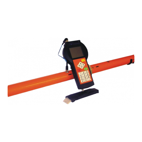
Control Unit The control unit can be assembled and used with any CMD probe. Battery charger status LCD display Power/backlight key Left/Right keys Up/Down keys No key Yes key Numeric keys Minus/decimal F-key point key Battery cover (PC + Flash disk) -
Page 8: Power Supply
User manual Power Supply The instrument can be supplied from: - exchangeable Li-Ion battery pack - six primary or NiCd or NiMh cells size AA (placed in the holder) - AC/DC adapter 120-240V, 50-60Hz - DC power source 12V, 1A (e.g. from a car socket) Use of a supply different from the accessories listed above or its self-made user modification can damage the device cancelling the warranty and is not recommended. -
Page 9: Switching The Instrument On/Off
Switching the instrument on/off The instrument is switched on by “Power” key. Then the following screen is shown. GF Instruments Conductivity Meter CMD Number of files: 131072 kB Free memory: Probe: CMD-4 (3.0 / 6.0m) SN-probe: #07070002 v1.0 #07070003 v1.1 SN-unit: Meas. -
Page 10: Display & Keys
User manual Display & Keys Display Backlight Backlight of the display can be switched on or off using “Power/Backlight” key. It improves the visibility of the display under worse light conditions but causes a quicker discharging of the batteries (about 10%) – thus it is recommended to use the backlight only if necessary. -
Page 11: Text Input
Text Input File: Locality: Note: Depth/Cal: F-Ground, Hi Meas. time: 2.0 s Meas. error: <1 % Text can be entered using numerical keys in a way similar to mobile phones. One of the signs available on the key can be chosen by its repeated pressing (within 1 s). -
Page 12: Input Of Numerical Values
User manual Input of Numerical Values File: Pruzkum 12 Locality: Brno Note: Depth/Cal: F-Ground, Hi 2.0 s Meas. time: <1 % Meas. error: Numerical values can be entered using keys “0“ to “9“ and “Minus/Decimal point“ key. If you want to insert minus sign, hold the F-key and press the “Minus/Decimal point”... -
Page 13: Gps Receiver Connection
Bluetooth port. The Bluetooth connection is available only if the port is not used for wireless connection with probe. If the GPS receiver is set correctly the CMD detects the GPS data automatically and displays them in the position window. - Page 14 User manual Turn your GPS receiver on. GPS receiver must be set to output NMEA protocol via Bluetooth connection. For GPS Pathfinder (Trimble), the Bluetooth 1 port is used. Press “Yes” key to continue the setting or “No” key to escape. The Control unit tries to connect Bluetooth device –...
-
Page 15: Probe
Wide family of CMD probes with various single or multidepth ranges is offered - CMD-Explorer, CMD-MiniExplorer, CMD-4/6, CMD-4, CMD-2, CMD- 1, CMD-Tiny and CMD-Duo. Each probe can measure both in the full depth range (vertical orientation of magnetic dipoles with the sensitivity at nominal depth) and in the half depth range (horizontal orientation of magnetic dipoles with the sensitivity near surface). - Page 16 User manual to one of two proper positions (HIGH, LOW) – two metal pins must fit with two holes in the probe. Tighten the white plastic screw back into the holder, connect the black plastic connector. Now the probe is ready for use. The connection between the probe and the control unit is provided via Bluetooth communication.
- Page 17 Insert the thinner part of the pulling rod with handle into the thicker one, lock the position using aluminum metal pin and screw the black plastic nut using slight force. Plastic nut Connect the pulling rod with the sledge. Assemble the joint according to the following picture.
-
Page 18: Probe Cmd-1 And Cmd-Miniexplorer
User manual Probe CMD-1 and CMD–MiniExplorer Connect the probe holder to the probe. If you wish to measure with maximum depth range (HIGH), turn the probe so that the black strip and label “Hi” are on the upper side. If you wish to measure with half depth range (LOW), turn the probe so that the black strip and label “Lo”... - Page 19 Then connect the probe and probe holder using short connection cable. The connection between the probe and the control unit is provided via Bluetooth communication. See the chapter Using Bluetooth adapter for remote control.
-
Page 20: Probes Cmd-2 And Cmd-4
(transmitter) to the left and the arm with shorter cover (receiver) to the right. In the case of CMD-4 the transmitter arm is labeled with simple black strip and the receiver with black “T”. Then connect the connector and assemble the arms by turning the bayonet rings. - Page 21 Fix the control unit to the probe. It is necessary to fix the holder to one of two proper positions (HIGH, LOW) – the fixing tip must be in one of two holes. Never try to use other position! Connect the probe and the control unit with the short cable from accessories.
- Page 22 User manual Now thread the belt through the belt holder which is on the upper side of the probe. For a longer work it is recommended to use the carrying harness from accessories. CMD-2 Control unit Belts CMD-4...
-
Page 23: Probe Cmd-4/6
Probe CMD–4/6 CMD-4/6 probe can be assembled to its maximum length to reach the effective depth range of 9 meters (CMD-6) or can be used with reduced length with the effective depth range of 6 meters (CMD-4). For CMD-4 assembling put three longer parts of the probe to each other having “T”... - Page 24 User manual Fix the control unit to the probe. It is necessary to fix the holder to one of two proper positions (HIGH, LOW) – the fixing tip must be in one of two holes. Never try to use other position! Connect the probe and the control unit with the short cable from accessories.
- Page 25 Now thread the belt through the belt holder which is on the upper side of the probe. For a longer work with the probe it is recommended to use the carrying harness from its accessories. Belts Control unit Metal bayonet maintenance Individual arms of the probe must be assembled using slight force with small clearance of connecting metal bayonet.
-
Page 26: Probe Cmd-Duo
User manual Probe CMD–Duo CMD-Duo can be assembled with three intercoil spacings to achieve three different depth ranges. Thus we can measure with 15, 30 or 60 m effective full depth range (Hi position) and 7.5, 15, or 30 m effective half depth range (Lo position). -
Page 27: Starting Up The Instrument
For easy field operation it is recommended to use coils with handles. Starting up the instrument Turn power switches at both coils on. Then switch on the control unit that must be always moved with the receiver coil (mutual Bluetooth connection). WARNING: Do not turn the instrument on when coils are close to each other (e.g. - Page 28 ). If the battery is discharged ( ) is shown, finish the current measurement and charge or exchange the battery. Critical discharge of any battery is signalized with periodic beeping. GF Instruments Conductivity Meter CMD Number of files: 131072 kB Free memory: Probe:...
-
Page 29: Battery Charging
Distance/reference cable replacing In the case of exchange of distance/reference cable turn the control unit off (transmitter and receiver coils will remain in standby mode) and replace the cable. Then switch the control unit on again. End of measurement When measurement is finished, first turn the control unit off, then turn the transmitter and the receiver off. -
Page 30: Battery Exchange
User manual Battery Exchange If you want to change the batteries, unscrew the four screws and remove cover of coil battery compartment. Then take out the Li-Ion battery pack, insert a new Li-Ion battery pack or AA battery holder instead and mount the cover back. -
Page 31: Probe Cmd-Explorer
Probe CMD–Explorer Put all four parts of the probe to each other having “T” and “I” marks in one line. Transmitter, which is labeled by “I”, is to be connected on the left side. Receiver, which is labeled by “T”, is to be connected on the right side. Two parts with the 5-pin connector (connection to the control unit) and buttons are in the middle. - Page 32 User manual Fix the control unit to the probe. It is necessary to fix the holder to one of two proper positions (HIGH, LOW) – the fixing tip must be in one of two holes. Never try to use other position! Connect the probe and the control unit with the short cable from accessories.
- Page 33 Now thread the belt through the belt holder which is on the upper side of the probe. For a longer work with the probe it is recommended to use the carrying harness from its accessories. Control unit Belts Metal bayonet maintenance Individual arms of the probe must be assembled using slight force with small clearance of connecting metal bayonet.
-
Page 34: Using Bluetooth Adapter For Remote Control
Using Bluetooth adapter for remote control Bluetooth adapter allows wireless connection of the control unit with the probe. It is possible to combine this adapter with any CMD probe. Bluetooth adapter is supplied from the same kind of batteries as the control unit, it contains integrated battery charger as well. -
Page 35: Battery Charging
. If the battery is discharged ( shown) finish the current measurement and charge or exchange the battery. Critical battery discharge is signalized with periodic beeping. GF Instruments Conductivity Meter CMD Number of files: 131072 kB Free memory: Probe: CMD-4 (3.0 / 6.0m) -
Page 36: Battery Exchange
User manual Battery Exchange The supply of the device from the Li-Ion battery pack delivered with the device (high capacity, good temperature characteristic and very low self-discharge) is recommended. Alternatively the supply from six alkaline cells of AA size (with the help of the battery holder from standard accessories) can be used. -
Page 37: Measurement
Measurement CMD instrument is designed both for manual spot measurement and for continuous measurement. The position can be entered manually or from GPS. It is possible to measure both continuous 2D areas and individual lines. The direction of measured lines can be uni- or bi- directional. See the picture below. -
Page 38: Calibrations & Depth
The CMD-MiniExplorer, CMD-1, CMD-Tiny and CMD- Duo are calibrated only on the ground surface. The CMD-Duo is not sensitive to the small change of level above the ground. It can be used both on the ground and at a certain level (up to 1m) above ground with the same calibration. - Page 39 In the CMD-Duo probe there are different names of calibrations: - F-10m, Hi factory calibration for 10m spacing for high depth range - F-10m, Lo factory calibration for 10m spacing for low depth range - F-20m, Hi factory calibration for 20m spacing for high depth range...
-
Page 40: Measurement Time & Speed Of Movement In The Field
Typical measurement, which uses 0.5 s measuring time and the speed of faster walker (5 km / h), gives 70 cm grid of measured points. CMD-Duo measuring time CMD-Duo measuring time can be set in the range 1 s to 20 s for all types of measurement. -
Page 41: Measurement Error
(with measuring tape) it is recommended to check the stability of individual values currently. Measurement error The measurement error is calculated as standard deviation. CMD allows activating automatic checking of measurement error. User can set the maximum acceptable measurement error in the range from 1 to 10 %. If the current measurement error is greater than set limit (<1%, <2%, <5%, <10%) the... -
Page 42: Measured Value Screens
User manual Measured value screens There are several screens for displaying currently measured values. User can change them during measurement to observe either numeric values or graphic information. The choice is done by pressing of “F” key together with one of “1–6” key. - Page 43 Window “F” + “3” shows position and measured values from three receivers. Only the highest standard deviation (from three receivers) is displayed. This window is available only if CMD-Explorer / MiniExplorer are used. St-dev[%] 0.0 m 0.0 m 21.3 mS/m 23.5...
- Page 44 (measured conductivities are out of range for inversion calculation – over 1000 mS/m, under 1 mS/m or too wide difference between measured conductivities). Only the highest standard deviation (from three receivers) is displayed. This window is available only if CMD-Explorer / MiniExplorer are used. St-dev[%] 0.0 m 0.0 m...
-
Page 45: Manual Measurement
(Meas. error). If you measure using CMD-Explorer / MiniExplorer, you are also asked to set the “Main view”, which determines the receiver shown in screens “1” and “2” during measurement. If you measure using CMD-Duo, you will be also able to change coil separation if needed. -
Page 46: Measuring Position
User manual Enter the x and y steps. X-step: 5.0 m Y-step: 5.0 m If you are going to measure in a grid of points (continuous area for 2D mapping) enter the distance of measured lines (x-step) and points in lines (y-step). If you are going to measure individual numbered lines only enter X-step=1 and Y-step as the distance of individual points on the line (thus x will show the number of line and Y the number of station then). - Page 47 The function of individual keys is following: - Yes / button on the probe – start of measurement. - No – enter of any measuring position or stop of the measurement – allows entering e.g. extra position which is not in the measuring grid (occurrence of an obstacle in field).
-
Page 48: Checking And Saving Data
User manual Checking and saving data X-position: 0.0 m Y-position: 0.0 m 21.3 mS Conduct.: 2.01 ppt In-phase: 0.2 % Meas. error: Save? Operator can check measured values and if they are OK he can put them into the memory pressing the button on the probe or by means of “Yes“ key. Then the following point coordinates are shown. -
Page 49: Continuous Measurement
Enter file name (obligatory), locality name and note (optional). Choose the calibration (Depth/Cal) and measurement time (Meas. time). If you measure using CMD-Explorer / MiniExplorer, you are also asked to set the “Main view”, which determines the receiver shown in screens “1” and “2” during measurement. If you measure using CMD-Duo, you will be also able to change coil separation, if needed. -
Page 50: Start Of The Measurement
User manual The next screen will be shown. X-step: 5.0 m Y-step: 5.0 m Enter the step of the length marks in their grid. If you are going to measure in a grid of length marks (continuous area for 2D mapping) enter the distance of length marks in x and y directions. - Page 51 The function of individual keys is following: - Yes /button on the probe – start of measurement. - No – enter of any position of the measurement beginning; respectively end of the measured file (if pressed three times). - Up / Down – movement of the starting position of the measurement to the next / previous length mark.
-
Page 52: Measurement Between Length Marks
Conduct.: 14.7 mS In-phase: 0.82 ppt CMD instrument measures continuously and saves data. During this measurement the operator must walk with a quasi-constant speed (at least between two following length marks). Speed difference causes adequate position error between those points. -
Page 53: Finishing Of The Line Measurement
Finishing of the line measurement At the end of the measured line press “No“ key. Then confirm or enter position of the last point (or press “No” key twice to continue the current line). >> LAST POINT << X-position: 120.0 m Y-position: 50.0 m The actual length mark position is offered as it is supposed to finish the... -
Page 54: Manual Measurement With Gps
Enter the file name (obligatory), locality name and note (optional). Choose the calibration (Depth/Cal). Set the measurement time (Meas. time) and measurement error limit (Meas. error). If you measure using CMD-Explorer / MiniExplorer, you are also asked to set the “Main view”, which determines the receiver shown in screens “1”... - Page 55 The next screen will appear: Latitude: 48 05.333N Longitude: 011 39.359E Conduct.: In-phase: Meas. error: Start measurement? Go to the measured point and press the button on the probe or “Yes“ key for start of the measurement. The functions of keys are following: - Yes / button on the probe –...
-
Page 56: Checking And Saving Measurement
User manual Checking and saving measurement Latitude: 48 05.333N Longitude: 011 39.359E 21.3 mS Conduct.: 2.01 ppt In-phase: 0.2 % Meas. error: Save? User can check measured values and if they are OK he can save them by means of the probe button or by “Yes“ key. Then it is possible to go to the next point. -
Page 57: Continuous Measurement With Gps
CMD-Explorer / MiniExplorer, you are also asked to set the “Main view”, which determines the receiver shown in screens “1” and “2” during measurement. If you measure using CMD-Duo, you will be also able to change coil separation, if needed. - Page 58 User manual The next screen will be shown. Latitude: 48 05.333N Longitude: 011 39.359E Point no.: Conduct.: In-phase: Start measurement? Go to the starting point and press the “Yes“ key for the start of the measurement. The functions of keys are following: - Yes –...
-
Page 59: The Current Measurement
Conduct.: 0.82 ppt In-phase: CMD instrument measures and saves data continuously together with GPS coordinates. The operator should keep a quasi-constant speed during measurement to cover the line regularly and to allow proper interpolating (e.g. in the case of GPS short drop-out). -
Page 60: Quick Search Measurement
(Meas. time). If you measure using CMD-Explorer / MiniExplorer, you are also asked to set the “Main view”, which determines the receiver shown in screen “1” during measurement. If you measure using CMD-Duo, you will be also able to change coil separation, if needed. - Page 61 – over 1000 mS/m, under 1 mS/m or too wide difference between measured conductivities). Screens 2 and 3 are available only if CMD-Explorer / MiniExplorer is used. - F-key + Up / Down – setting of the scale for conductivity.
-
Page 62: File Tools
User manual File Tools This option allows showing measured data, deleting files from the memory (step by step or at once) and saving measured files into USB – Flash disk. Visualization of measured data Choose “File Tools” from the main menu and then “File View“. Choose a file that you wish to see then and confirm it by “Yes”... -
Page 63: Saving Stored Files Into Usb-Flash Disk
Saving stored files into USB-Flash disk CMD control unit allows saving all measured files from internal memory to standard USB-Flash disk. The Flash disk sector size must be 512 Bytes (usual sector size). The Flash disk can be formatted to FAT12, FAT16 or FAT32 file system, cluster size up to 32 kB. - Page 64 User manual Select path where new project folder will be created. Already existing directories are displayed. Use “Up/Down” keys to select any of them. Use “Right” key to go into selected folder. Use “Left” key to go back to previous folder. The current path is displayed above the line.
-
Page 65: Creating New Calibration
It is recommended to find and fix your own calibrating points after the purchase of the CMD instrument to be able either to check the instrument calibration from time to time or to create a user calibration. Each calibration is two-point. It is necessary to make the calibration on a site with homogenous structure. - Page 66 (It takes approximately 1 min) the next screen is shown. Conductivity [mS/m]: Point 1 L: 10.0 The screen differs if you are calibrating CMD-Explorer / MiniExplorer, which consists of three independent receivers: Conductivity [mS/m]: Shortest dip.: 10.0 Receiver 2: 10.0...
-
Page 67: Remeasure Any Calibration Point
Enter new conductivity values in mS/m of all measured points. After that confirm whether you wish to save the calibration by means of “Yes“ key. If you want to change conductivity values stored in CMD-Explorer / MiniExplorer, before asking for new conductivity values you are asked to choose... -
Page 68: Deleting The Calibration
User manual Deleting the calibration Choose “Setting“ from the main menu, choose appropriate calibration from a list of calibrations and then “Delete calibration” and confirm it by “Yes“ key. It is not possible to use deleted calibration for next measurement. -
Page 69: Data Download
Data Download Software installation Insert the installation CD called CMD into the PC. Connect PC with CMD control unit by means of USB cable from accessories and turn the instrument on. Wait till the dialog “Found new hardware” appears and continue installing driver according to instructions shown (For more details see the “readme.txt”... -
Page 70: Choosing Proper Version Of Binary File
“File”. - The right upper window displays all files stored in the selected folder. Exported data files are placed under CMD binary files (extension .bin) from which they were exported. It is possible to rename or delete any file or to export data from selected binary file using context menu (mouse right button click) or using menu “File”... -
Page 71: Download Of Measured Files
Run PC software by clicking the icon “CMD Data Transfer” (on the PC screen or in the menu “Start \ All programs \ GF Instruments \ CMD Data Transfer“). The main window of the CMD software is shown. Select the folder for data storing, select export data format eventually which data files should be exported automatically during data downloading. -
Page 72: Exporting Data To Interpretation Programs
User manual Exporting data to interpretation programs It is possible to export data from binary file to various contouring or inversion programs. Different data files can by created automatically during data download as well as manually any time later from stored binary file. To set any type to be exported automatically mark appropriate file in the menu “Export settings”... - Page 73 - “Surfer data format” – You can set the maximum depth and the number of layers to be exported (files srf_map.dat a srf_prfl.dat). Different values can be set for CMD – Explorer / MiniExplorer as well as for Surfer – Map / Profile.
-
Page 74: Exported File Types
Primary position without interpolation (X, Y or Lat, Lon, Alt), measured values (conductivity or resistivity, in-phase, measurement error) and note. CMD Explorer / MiniExplorer also stores results of two-layered 1D inversion (conductivity of the first layer, conductivity of the bottom layer, thickness of the first layer and RMS error of the inversion). - Page 75 - .srf_map.dat – is ASCII file for 3D mapping using XYZ contouring software. This file is generated only from CMD-Explorer / MiniExplorer measurements. The measured conductivity (apparent conductivity as well as the true conductivity – the result of built-in in-situ 1D inversion) is distributed between depth layers.
- Page 76 6 m / 6 (12) layers CMD- Explorer / Low depth range: 3 m / 6 layers CMD-MiniExplorer / High depth range: 2 m / 6 (12) layers CMD-MiniExplorer / Low depth range: 1 m / 6 layers - .interpolated.srf_map.dat is ASCII file like “.srf_map.dat”. This file is generated only from continuous measurements (both manual and GPS).
- Page 77 - .srf_prfl.dat – is ASCII file for 2D profile mapping using XYZ contouring software. This file is generated only from CMD-Explorer / MiniExplorer measurements. The measured conductivity (apparent conductivity as well as the true conductivity – the result of built-in in-situ 1D inversion) is distributed between individual depths.
- Page 78 - .res2D.dat is ASCII file allowing compiling data using Res2DInv software. This file is generated only from CMD-Explorer / MiniExplorer measurements. Measured conductivities are converted to resistivities as they would be measured by geoelectrical instrument using Wenner- Schlumberger array.
-
Page 79: Firmware Upgrade
#07070003 v1.1 SN-unit: Meas. error: Connect CMD control unit (switched off) with PC by means of USB cable from accessories (to the round middle connector of the control unit). USB (PC) Leave the probe disconnected if you want to upgrade firmware in the Control Unit or connect the Probe to the Control Unit if you want to upgrade firmware in the Probe. - Page 80 Run PC software by clicking the icon “CMD Data Transfer“ (on the PC screen or in the menu “Start \ All programs \ GF Instruments \ CMD Data Transfer“). The main window of the CMD software is shown.
-
Page 81: Combining Newer - Older Control Unit And Probe
Connect cable to the Control Unit probe connector, as shown in the figure below. After upgrade finish connect cable back and fix the connector, include the battery and fix the cover. Combining newer - older control unit and Probe If older control unit (older than v2.0) or older probe (older than v2.0) is connected with newer probe/control unit, the system works as both control unit and the probe are older. -
Page 82: Technical Specification
User manual Technical specification Control unit Attachable CMD control unit works with all types of probes Five modes of measurements: o Manual measurement – the user starts measurement at each point by pressing the key or by buttons. The point position is updated automatically in the preset grid or can be entered directly. -
Page 83: Standard Control Unit Accessories
o max. 4.8 millions measured points Graphical LCD display 320x240, white backlight Easy USB data transfer Power supply: o Internal exchangeable rechargeable lithium-ion battery pack. (Integrated fully automatic intelligent battery charger activated by the connection of external 12 V source.) o Working time: 3 –... -
Page 84: Probe
CMD-Explorer 2.2 – 4.2 – 6.7 m / 1.1 – 2.1 – 3.3 m CMD-MiniExplorer 0.5 – 1.0 – 1.8 m / 0.25 – 0.5 – 0.9 m CMD-Duo 15 – 30 – 60 m / 7,5 – 15 – 30 m ... - Page 85 CMD-4: 3.77 m CMD-4/6: 3.77 / 5.79 m CMD-Explorer 1.48 m / 2.82 m / 4.49 m CMD-MiniExplorer 0.32 m / 0.71 m / 1.18 m CMD-Duo 10 m / 20m / 40m Probe length & weight: CMD-Tiny: 500 mm, 400 g CMD-1: 1 065 mm, 2.5 kg...
-
Page 86: Standard Probe Accessories
Probe holder (CMD-1, CMD-Tiny, CMD-MiniExplorer) Connection cable Carrying handles (CMD-Duo) Three distance/reference cables for 10 m, 20 m, 40 m separations (CMD-Duo) Spare battery for transmitter with charger (CMD-Duo) Optional accessories: Bluetooth adapter for wireless communication with probe ... -
Page 87: Store And Transport
Store and transport It is strongly recommended to store and transport the CMD instrument disassembled and placed in the original box. If the device is not used for a long time, for example during winter, it is recommended to store it in a dry room. Before the storage and before next use it should be fully charged if the Li-Ion battery pack is used.
Need help?
Do you have a question about the CMD and is the answer not in the manual?
Questions and answers