
Related Manuals for SIGMATEK AI 040


Summary of Contents for SIGMATEK AI 040
- Page 1 AI 040 S-DIAS Analog Input Module Instruction Manual Date of creation: 16.01.2015 Version date: 26.07.2023 Article number: 20-009-040-E...
- Page 2 (print, photocopy, microfilm or in any other process) without the express permission. We reserve the right to make changes in the content without notice. The SIGMATEK GmbH & Co KG is not responsi- ble for technical or printing errors in the handbook and assumes no responsibility for damages that occur through...
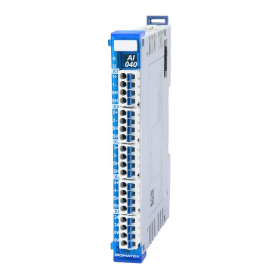
- Page 3 S-DIAS ANALOG INPUT MODULE AI 040 S-DIAS Analog Input Module AI 040 with 4 inputs for vibration sensors with IEPE interface The S-DIAS AI 040 analog input module has four constant current sources, which independently another. The sensor signals converted to a broad frequency range with a 16-bit resolution.
-
Page 4: Table Of Contents
AI 040 S-DIAS ANALOG INPUT MODULE Contents Introduction ................5 Target Group/Purpose of this Operating Manual ...... 5 Important Reference Documentation ......... 5 Contents of Delivery ..............5 Basic Safety Directives ............6 Symbols Used ................6 Disclaimer ..................8 General Safety Directives ............ - Page 5 S-DIAS ANALOG INPUT MODULE AI 040 Environmental Conditions ............18 Mechanical Dimensions ............19 Connector Layout ..............20 Status LEDs ................. 21 Applicable Connectors ............... 22 Label Field ................... 23 Wiring ..................24 Wiring Example ................24 Note ....................25 Schematic Diagram..............
- Page 6 AI 040 S-DIAS ANALOG INPUT MODULE 13 Storage ...................34 14 Maintenance ................35 14.1 Service ..................35 14.2 Repair ................... 35 15 Disposal ..................35 16 Hardware Class AI040 ............36 16.1 General ..................37 16.2 Analog Inputs [1-4] ..............38 16.2.1 Communication Interfaces ..............39 16.3...
-
Page 7: Introduction
General knowledge of automation technology is required. Further help and training information, as well as the appropriate accessories can be found on our website www.sigmatek-automation.com. Our support team is happily available to answer your questions. Please see our website for our hotline number and business hours. -
Page 8: Basic Safety Directives
AI 040 S-DIAS ANALOG INPUT MODULE Basic Safety Directives Symbols Used The following symbols are used in the operator documentation for warning and danger messages, as well as informational notes: DANGER Danger indicates that death or serious injury will occur, if the speci- fied measures are not taken. - Page 9 S-DIAS ANALOG INPUT MODULE AI 040 INFORMATION Information Provides important information on the product, handling or relevant sections of the documentation, which require atten- tion. 26.07.2023 Page 7...
-
Page 10: Disclaimer
It does not guarantee properties under the warranty. Please thoroughly read the corresponding documents and this operat- ing manual before handling a product. SIGMATEK GmbH & Co KG is not liable for damages caused through, non-compliance with these instructions or applicable regulations. -
Page 11: General Safety Directives
S-DIAS ANALOG INPUT MODULE AI 040 General Safety Directives The Safety Directives in the other sections of this operating manual must be observed. These instructions are visually emphasized by symbols. INFORMATION According to EU Directives, the operating manual is a component of a product. -
Page 12: Software/Training
AI 040 S-DIAS ANALOG INPUT MODULE CAUTION Handle the device with care and do not drop or let fall. Prevent foreign bodies and fluids from entering the device. The device must not be opened! Manipulez l’appareil avec précaution et ne le laissez pas tomber. -
Page 13: Standards And Directives
The product was constructed in compliance with the following European Union directives and tested for conformity. 3.1.1 EU Conformity Declaration EU Declaration of Conformity The product AI 040 conforms to the following European directives: • 2014/35/EU Low-voltage Directive • 2014/30/EU Electromagnetic Compatibility (EMC Directive) •... -
Page 14: Type Plate
AI 040 S-DIAS ANALOG INPUT MODULE Type Plate HW: Hardware version SW: Software version Page 12 26.07.2023... -
Page 15: Technical Data
S-DIAS ANALOG INPUT MODULE AI 040 Technical Data IEPE Interface Specifications Number of channels Measurement Range ±5.500 V ±2.750 V ±1.375 V ±0.688 V ±0.344 V ±0.172 V Adjustable amplification Measurement value ±30000 An open or shorted input returns -2147483632 in the hardware class. -
Page 16: Input Filter Hardware
AI 040 S-DIAS ANALOG INPUT MODULE Input Filter Hardware Page 14 26.07.2023... -
Page 17: Software Band Pass Filter Specifications
S-DIAS ANALOG INPUT MODULE AI 040 Software Band Pass Filter Specifications Lower frequency limit adjustable (min 0.1 Hz) Upper frequency limit adjustable (max. 10 kHz) Measurement values configurable processed per cycle Output parameters average value minimum value maximum value time stamp minimum value time stamp maximal value The filter block can be used for every channel, as well as several times per channel. -
Page 18: Measuring And Bus Transmission
AI 040 S-DIAS ANALOG INPUT MODULE Measuring and Bus Transmission In the module, values are measured continuously. Data is transferred isochronously. All recorded values are therefore available in every bus cycle. The following data is generated with a bus time of 1 ms. - Page 19 S-DIAS ANALOG INPUT MODULE AI 040 26.07.2023 Page 17...
-
Page 20: Miscellaneous
AI 040 S-DIAS ANALOG INPUT MODULE Miscellaneous Article number 20-009-040 Standard UL 508 (E247993) Approbations UL, cUL, CE, UKCA Environmental Conditions Storage temperature -20 ... +85 °C Environmental temperature 0 ... +60 °C Humidity 0-95 %, non-condensing Installation altitude above sea... -
Page 21: Mechanical Dimensions
S-DIAS ANALOG INPUT MODULE AI 040 Mechanical Dimensions 26.07.2023 Page 19... -
Page 22: Connector Layout
AI 040 S-DIAS ANALOG INPUT MODULE Connector Layout INFORMATION The connections of the +24 V supply (X5: pin 1 and pin 2) or the GND supply (X5: pin 3 and pin 4) are internally bridged. To supply the mod- ule, only one connection to a +24 V pin (pin 1 or pin 2) and a GND pin (pin 3 or pin 4) is required. -
Page 23: Status Leds
S-DIAS ANALOG INPUT MODULE AI 040 Status LEDs Module Status green module active no supply available BLINKING (5 Hz) no communication User yellow can be set from the application (e.g. the module LED can be set to blinking through the visuali-... -
Page 24: Applicable Connectors
AI 040 S-DIAS ANALOG INPUT MODULE Applicable Connectors Connectors: X1-X5: Connectors with spring terminals (included in delivery) The spring terminals are suitable connecting ultrasonically compacted (ultrasonically weld- ed) strands. Connections: Stripping length/Sleeve length: 10 mm Mating direction: parallel to the lead axis or circuit board Conductor cross section, rigid: 0.2-1.5 mm... -
Page 25: Label Field
S-DIAS ANALOG INPUT MODULE AI 040 Label Field Manufacturer Weidmüller Type MF 10/5 CABUR MC NE WS Weidmüller article number 1854510000 Compatible printer Weidmüller Type Printjet Advanced 230V Weidmüller article number 1324380000 26.07.2023 Page 23... -
Page 26: Wiring
AI 040 S-DIAS ANALOG INPUT MODULE Wiring Wiring Example Page 24 26.07.2023... -
Page 27: Note
S-DIAS ANALOG INPUT MODULE AI 040 Note The signals recorded by the analog modules are very small, as compared to the digital signals. To ensure error-free operation, a careful wiring method must be followed: • The DIN rail must have an adequate mass connection. -
Page 28: Schematic Diagram
AI 040 S-DIAS ANALOG INPUT MODULE Schematic Diagram Page 26 26.07.2023... -
Page 29: Assembly/Installation
S-DIAS ANALOG INPUT MODULE AI 040 Assembly/Installation Check Contents of Delivery Ensure that the contents of the delivery are complete and intact. See chapter Contents of Delivery. INFORMATION On receipt and before initial use, check the device for damage. If the device is damaged, contact our customer service and do not install the device in your system. -
Page 30: Mounting
AI 040 S-DIAS ANALOG INPUT MODULE Mounting The S-DIAS modules are designed for installation into the control cabinet. To mount the modules a DIN-rail is required. The DIN rail must establish a conductive connection with the back wall of the control cabinet. The individual S-DIAS modules are mounted on the DIN rail as a block and secured with latches. - Page 31 S-DIAS ANALOG INPUT MODULE AI 040 Recommended minimum distances of the S-DIAS modules to the surrounding components or control cabinet wall: a, b, c … distances in mm (inches) 26.07.2023 Page 29...
-
Page 32: Addressing
AI 040 S-DIAS ANALOG INPUT MODULE 10 Addressing 10.1 Address Mapping Overview Address Size Device ID Description Software (hex) (bytes) (thex) Access Control 0000 0138 SPI Master 0140 0E07 S-DIAS Sync Generator 0180 0907 S-DIAS configuration register Memory 0000 Register data FiFo... - Page 33 S-DIAS ANALOG INPUT MODULE AI 040 0201 DC OK Register Bit 0 DC 5 V ok Bit 1 DC 24 V ok Bit 2 DC 5 V not ok latched Bit 3 DC 24 V not ok latched Bit 4-7...
- Page 34 AI 040 S-DIAS ANALOG INPUT MODULE 0208 Hardware control register channel 2 Bit 0-2 Current amplifier Bit 3 Reserved Bit 4-5 Constant current source Bit 6-7 Reserved 0209 Hardware control register channel 3 Bit 0-2 Current amplifier Bit 3 Reserved...
-
Page 35: Supported Cycle Times
S-DIAS ANALOG INPUT MODULE AI 040 11 Supported Cycle Times 11.1 Cycle Times below 1 ms (in µs) x= supported 11.2 Cycle Times equal to or higher than 1 ms (in ms) x= supported x= supported 26.07.2023 Page 33... -
Page 36: Transport/Storage
AI 040 S-DIAS ANALOG INPUT MODULE 12 Transport/Storage INFORMATION This device contains sensitive electronics. During transport and stor- age, high mechanical stress must therefore be avoided. For storage and transport, the same values for humidity and vibration as for operation must be maintained! Temperature and humidity fluctuations may occur during transport. -
Page 37: Maintenance
S-DIAS ANALOG INPUT MODULE AI 040 14 Maintenance INFORMATION During maintenance as well as servicing, observe the safety instruc- tions from chapter 2 Basic Safety Directives. 14.1 Service This product was constructed for low-maintenance operation. 14.2 Repair INFORMATION In the event of a defect/repair, send the device with a detailed error description to the address listed at the beginning of this document. -
Page 38: Hardware Class Ai040
AI 040 S-DIAS ANALOG INPUT MODULE 16 Hardware Class AI040 Hardware Class AI040 for the S-DIAS AI040 analog module Page 36 26.07.2023... -
Page 39: General
S-DIAS ANALOG INPUT MODULE AI 040 This hardware class is used to control the AI 040 hardware module. The module has four analog inputs and four 1024-byte Fifo buffers. The measurement value of each analog input is written into the corresponding Fifo buffer. To evaluate the Fifo buffer, the AI 040 band pass filter hardware class can be used. -
Page 40: Analog Inputs [1-4]
AI 040 S-DIAS ANALOG INPUT MODULE 16.2 Analog Inputs [1-4] AnalogInput Input Analog input. Here, the first value from the Fifo buffer is displayed. The value displayed is dependent on State Gain and the properties MaxValue and MinValue. An open or shorted input returns -2147483632 in the hardware class. -
Page 41: Communication Interfaces
S-DIAS ANALOG INPUT MODULE AI 040 16.2.1 Communication Interfaces ALARM Downlink With this downlink the corresponding alarm class can be placed via the hardware editor. 16.3 Global Methods The following methods can be called via the ClassState server. 16.3.1 GetData... -
Page 42: Getsettings
AI 040 S-DIAS ANALOG INPUT MODULE 16.3.2 GetSettings This function is used to read the module settings. Transfer parameters Type Description usChannelNr USINT Indicates the analog input, from which the multiplier and divisor must be used. pSampleRate ^LREAL Pointer to which the scan rate of the analog input is written. -
Page 43: Internal Properties
S-DIAS ANALOG INPUT MODULE AI 040 16.4 Internal Properties The shortest conversion time of the ADC is 5 microseconds. In one millisecond, a maximum of 200 values can be thereby converted. If all 4 analog inputs are active, then 50 measure- ment values per channel per cycle are processed. -
Page 44: Special Case: 3 Analog Inputs Activated
AI 040 S-DIAS ANALOG INPUT MODULE 16.4.3 Special case: 3 analog inputs activated With a cycle time of 1 ms, 66.67 measurement values are generated per cycle. In this case, a warning is triggered and the timing changes. In this case, the last value in the buffer is discarded. -
Page 45: Hardware Class Ai040Bandpassfilter
This hardware class is used for calculating the band pass filter in the measurement values from the FIFO buffer of the AI 040 module. The real-time task of the object is thereby auto- matically set to the bus cycle time. -
Page 46: Servers
AI 040 S-DIAS ANALOG INPUT MODULE 17.1.2 Servers ClassState This server shows the actual status of the hardware class. ResonanceFrequ This server shows the resonance frequency in 1/10 Hz. qFactor This server shows the quality factor in 1/1000. Maximum This server shows the current maximum of the filtered values. -
Page 47: Global Methods
S-DIAS ANALOG INPUT MODULE AI 040 17.2 Global Methods The following methods can be called via the ClassState server. 17.2.1 GetValues This function is used to retrieve the filtered and unfiltered values. Transfer parameters Type Description pRawValues ^INT Pointer to the unfiltered value to copy. Only used when a valid pointer is entered. - Page 48 AI 040 S-DIAS ANALOG INPUT MODULE With the multiple filter cycles, the real-time also increases. In the diagram below, the real- time load was recorded in µs with 50, 100 and 200 measurement values and 1-4 filter cy- cles. The CP 111 was used as the CPU.
- Page 49 S-DIAS ANALOG INPUT MODULE AI 040 Documentation Changes Change date Affected Chapter Note page(s) 30.01.2015 4.2 note Note regarding connecting/disconnecting the S-DIAS module under voltage. 26.03.2015 3.2 Applicable Connectors Connections expanded 30.03.2015 1.1 IEPE Interface Specifica- Measurement range, adjustable amplification, meas-...
- Page 50 AI 040 S-DIAS ANALOG INPUT MODULE 06.12.2022 1.7 Miscellaneous UKCA conformity 26.07.2023 Document General chapters added, design Page 48 26.07.2023...
Need help?
Do you have a question about the AI 040 and is the answer not in the manual?
Questions and answers