ROLEC Sinexcel ULTRACHARGE 160 Installation & Operation Manual
Intelligent ultra-rapid ev charging station
Hide thumbs
Also See for Sinexcel ULTRACHARGE 160:
- Maintenance manual (24 pages) ,
- Maintenance manual (24 pages)

Related Manuals for ROLEC Sinexcel ULTRACHARGE 160


Summary of Contents for ROLEC Sinexcel ULTRACHARGE 160
- Page 1 INSTALLATION & OPERATION MANUAL ULTRACHARGE 160 Stocked in Intelligent ultra-rapid EV charging station the UK by...
-
Page 2: Product Support
Date Published: October 2023 Rolec Services Ltd are the publishers of this document and own the rights to use the text, images and all technical content contained within. Content supplied by third parties / partner organisations remains the property of that organisation and is used by agreement with the supplier. -
Page 3: Table Of Contents
Product Support Contents Product Support Safety Safety Advice Within this Manual Disclaimer Equipment Warnings Safety Instructions for Use Safety Instructions for Operation Product Overview Short description Charger Models Product Views Product Characteristics Product Specifications Installation instructions Equipment Dimensions Equipment Installation Requirements Distribution Cables Layout Requirements of Distribution Cables Requirements for Distribution Cables... -
Page 4: Safety
Damage to the product may render it unsafe. The product must be electrically isolated and NOT used until appropriate remedial action has been performed. Rolec does NOT recommend the use of charging extension cables or adapters and their use may invalidate the charge point warranty. -
Page 5: Disclaimer
Disclaimer Disclaimer Rolec shall not be liable for personal injury, product damage, failure or defects in scenarios such as but not limited to: Installation and/or maintenance performed by unlicensed/unqualified personnel. Lack of appropriate maintenance in accordance with the maintenance manual. -
Page 6: Equipment Warnings
Equipment Warnings Equipment Warnings Symbol Meaning Description Parts of the system are at High Power during operation. DANGER Direct or indirect contact with these components can be fatal. High voltage area may cause fire or electric shock. The construction of the area and conduits for cables must DANGER comply with national legislation. -
Page 7: Safety Instructions For Use
Pay attention to the safety symbols on the equipment and all the safety instructions in this document. When operating equipment has encountered any problems or faults, please contact Rolec Technical Support directly. Unauthorized third-party maintenance will invalidate the warranty, Makes sure the unit is not installed near to potentially dangerous equipment or other hazards. - Page 8 Safety Instructions for Operation Do not use this product if the power cord or connector shows any signs of damage. In case of any abnormal operation or conditions, press the emergency button immediately to turn off all electrical input and output. If the emergency button is pressed, the system operator should be informed.
-
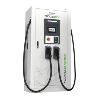
Page 9: Product Overview
Product Overview Product Overview Short description The UltraCharge 160 is an integrated DC fast charger that features high efficiency and flexible configuration. It supports the charging of two vehicles at the same time at same time and meets the charging demand of larger capacity and high endurance electric vehicles. - Page 10 Product Overview Eye Bolts for Lifting Status LED Screen Emergency Button Door Handle/Lock Charging Connector Antenna Payment Card Reader Air Outlet Figure 2 External Components Main Circuit Breaker AC Incoming Copper Bar Inlet Hole Grounding Bar Figure 3 Internal Components UltraCharge 160 DC Charger EVUCM-001-V01R1 Installation and Operation Manual Page 9 of 30...
-
Page 11: Product Characteristics
Product Characteristics Product Characteristics A variety of power configurations from 60kW to 160kW. Flexible power distribution – the dual connector model can automatically switch the power according to the vehicle demand, and the rapid charging of two vehicles at the same time. The constant current and constant power charging methods have the advantages of high charging efficiency, simple operation and reliable performance. -
Page 12: Product Specifications
Product Characteristics Product Specifications Item Parameter Category Input 3P+N+PE Input Voltage AC 380~400V Input Characteristic Frequency 50/60Hz Power Factor 0.99 THDi <5% CCS2 : 200-1000 Vdc Output Voltage CHAdeMO: 200-500Vdc Rated power 60-160kW Output Characteristic CCS2 : 200A Max Current CHAdeMO: 125A &... -
Page 13: Installation Instructions
Installation instructions Installation instructions Equipment Dimensions Figure 4 Outline and Dimension of Charger Figure 5 Hole Size of Charger Base EVUCM-001-V01R1 Installation and Operation Manual UltraCharge 160 DC Charger Page 12 of 30 October 2023... -
Page 14: Equipment Installation Requirements
Installation instructions Equipment Installation Requirements 1. The charger can be opened at the front, left and right-hand sides and charging connectors can used from both sides. 2. Space should be reserved around. See Figure 8. 3. Installation should be onto a foundation of channel steel or concrete. The cable shall be embedded in advance The reserved length of Ethernet cable should not be less than 4000mm. -
Page 15: Distribution Cables
Installation instructions Figure 7 Base and Cable Reservation Requirements Distribution Cables Layout Requirements of Distribution Cables 1. The incoming cable(s) should be laid through a cable trench and should enter charge point enclosure through the inlet hole at the bottom of the charger. 2. -
Page 16: Requirements For Distribution Cables
Installation instructions Requirements for Distribution Cables 1. Cable laying shall be free from external force, distortion and damage of the insulation layer. Do NOT twist, flatten, break or abrade the protective layer. 3. The protective pipe must be cleaned before the cable passes through and the wire must not be damaged. -
Page 17: Internal Wiring
Installation instructions Internal Wiring The internal input cables are N, L1, L2, L3, PE, Ctrl and Eth from left to right. The ‘Ctrl’ indicates a control signal cable and the ‘Eth’ indicates a ethernet cable. The cabinet grounding is divided into two parts, Grounding bar inside the cabinet Grounding of cabinet shell. -
Page 18: Installation
Installation instructions Installation Tools required Claw hammer Cross screwdriver Step ladder Electric drill Insulating gloves Cable clipper Insulation shoes Hydraulic clamp Adjustable wrench Security Hex wrench Craft knife Unpacking the Outer Package of the Cabinet 1. Straighten the metal tabs on the top of the packing material and remove the upper panel. - Page 19 Installation instructions 3. Carefully cut the plastic bags wrapped around the cabinet and remove the PE bags and foam Figure 10 Unpacking 2 4. Remove the four M12 bolts around the base Figure 11 Unpacking 3 EVUCM-001-V01R1 Installation and Operation Manual UltraCharge 160 DC Charger Page 18 of 30 October 2023...
-
Page 20: Foundation Drilling
Installation instructions Foundation Drilling The hole size is shown below: Figure 12 Foundation Preparation 1 1. Drill four mounting holes with a diameter of 16 mm and a depth of 80-85 mm on the cement mounting base. 2. Knock four M12 * 80 expansion bolts into the holes. Figure 13 Foundation Preparation 2 UltraCharge 160 DC Charger EVUCM-001-V01R1 Installation and Operation Manual... -
Page 21: Site The Charger
Installation instructions Site the Charger 1. Use forklift to transport the cabinet to the installation base and use the crane to lift the cabinet. Figure 14 Site Location 1 2. Suspend the cabinet above the cement base, open the front door of the cabinet, and extend the embedded cable from the bottom of the cabinet through the inlet hole. - Page 22 Installation instructions Figure 15 Site Location 2 NOTES: Match the mounting hole of the cabinet base with the hole on the cement base. The inlet cable sealing plate of the cabinet can be removed. To remove the sealing plate, pull the cables into the cabinet through the cable inlet hole, Install the sealing plate and pass the cables through the cable gland Secure the sealing plate to ensure airtightness.
- Page 23 Installation instructions 4. Install M12 * 80 (4 pcs) expansion bolts on the drilled installation holes around the base and tighten the bolts to ensure the cabinet is fixed securely. Figure 17 Site Location 4 5. Install the front and rear sealing plates of the base. Figure 18 Site Location 5 EVUCM-001-V01R1 Installation and Operation Manual UltraCharge 160 DC Charger...
- Page 24 Installation instructions NOTE: Install the front and rear sealing plates in the direction of the arrow, and then install the M6 * 15 screws from the left and right sides. 6. Install the left and right sealing plates. Figure 19 Site Location 6 UltraCharge 160 DC Charger EVUCM-001-V01R1 Installation and Operation Manual Page 23 of 30...
-
Page 25: Inspection After Installation
Installation instructions Inspection After Installation Stability After the pedestal is installed, shake the cabinet from different directions. There should be no obvious loosening and shaking. Clean Up Dispose of all transportation and packaging materials in accordance with local regulations. Clean up the sundries inside and around the cabinet, such as small section of cable, binding tape, screw / nut, desiccant, etc. -
Page 26: Operation Interface
Operation Interface Operation Interface Charging Process NOTE: When the charger is in standby mode, the screen is in the energy-saving mode. Before operation, touch the screen with your finger to light up the screen! Standby Interface 1. Select CCS connector or CHAdeMO (JAP) connector according to the socket type of the car. - Page 27 Operation Interface 2. Click Next to enter the interface for charging mode selection. 3. Click the payment method you want to use to enter the next charging operation. EVUCM-001-V01R1 Installation and Operation Manual UltraCharge 160 DC Charger Page 26 of 30 October 2023...
-
Page 28: Code Scanning Charging Interface Process
Operation Interface Code Scanning Charging Interface Process 1. Scan the QR to enter the start charging interface. Charging interface 2. Click "End" to end charging and enter the settlement interface. Tip: After charging, click the Back button. If the other charging connector is in charging state, it will jump to the charging interface of the other charging connector, otherwise it will jump to the main interface. -
Page 29: Interface Process Of Pay By Card Charging
Operation Interface Interface Process of Pay by Card Charging 1. Select or enter the precharge amount to enter the card swiping interface. Pay by card according to the interface prompt Charging to enter the charging interface. start interface. Click End to end charging and enter the pay by card interface. -
Page 30: Password Charging Interface Process
Operation Interface Password charging interface process 1. Enter the password to enter the start charging interface. Charging interface. 2. Click "End" to end charging and enter the pay interface. Tip: Click the input box to display a small keyboard. Enter the complete password through the keyboard and click OK to verify the password. -
Page 31: Simple Troubleshooting
Simple Troubleshooting Simple Troubleshooting Refer to the maintenance manual for further details. Alarm or Fault Processing Method Check the status of lightning protection. Lightning protection failure If the visual window of lightning protection is red, it means it is damaged, please replace it. Check the position of the emergency stop button. - Page 32 Brand names, logos and trademarks used herein remain the property of their respective owners. This listing of any firm or their logos is not intended to imply any endorsement or direct affiliation with Rolec Services Ltd. and is purely to demonstrate branding opportunities. © 2023 by Rolec Services. All rights reserved.
Need help?
Do you have a question about the Sinexcel ULTRACHARGE 160 and is the answer not in the manual?
Questions and answers