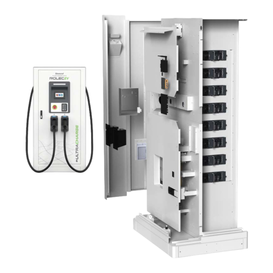
ROLEC Sinexcel ULTRACHARGE 160 Maintenance Manual
Intelligent ultra-rapid ev charging station
Hide thumbs
Also See for Sinexcel ULTRACHARGE 160:
- Installation & operation manual (32 pages) ,
- Maintenance manual (24 pages)

Related Manuals for ROLEC Sinexcel ULTRACHARGE 160


Summary of Contents for ROLEC Sinexcel ULTRACHARGE 160
- Page 1 MAINTENANCE MANUAL ULTRACHARGE 160 Stocked in Intelligent ultra-rapid EV charging station the UK by...
-
Page 2: Product Support
Date Published: October 2023 Rolec Services Ltd are the publishers of this document and own the rights to use the text, images and all technical content contained within. Content supplied by third parties / partner organisations remains the property of that organisation and is used by agreement with the supplier. -
Page 3: Table Of Contents
Product Support Contents Product Support Safety Safety Advice Within this Manual Disclaimer Equipment Warnings Safety Instructions for Use Safety Instructions for Operation Maintenance Maintenance of Inactive Charging Stations Charger Checks and Maintenance Cycle Replacement of Common Devices Electric Meter Main circuit breaker Cooling fan AC contactor Current transformer... -
Page 4: Safety
Damage to the product may render it unsafe. The product must be electrically isolated and NOT used until appropriate remedial action has been performed. Rolec does NOT recommend the use of charging extension cables or adapters and their use may invalidate the charge point warranty. -
Page 5: Disclaimer
Warnings, Cautions and Notes may be repeated several times as appropriate and may be preceded by a hazard symbol where appropriate. Disclaimer Rolec shall not be liable for personal injury, product damage, failure or defects in scenarios such as but not limited to: Installation and/or maintenance performed by unlicensed/unqualified personnel. -
Page 6: Equipment Warnings
Equipment Warnings Equipment Warnings Symbol Meaning Description Parts of the system are at High Power during operation. DANGER Direct or indirect contact with these components can be fatal. High voltage area may cause fire or electric shock. The construction of the area and conduits for cables must DANGER comply with national legislation. -
Page 7: Safety Instructions For Use
Pay attention to the safety symbols on the equipment and all the safety instructions in this document. When operating equipment has encountered any problems or faults, please contact Rolec Technical Support directly. Unauthorized third-party maintenance will invalidate the warranty, Makes sure the unit is not installed near to potentially dangerous equipment or other hazards. -
Page 8: Safety Instructions For Operation
Safety Instructions for Operation Safety Instructions for Operation Before using for the first time, you must read this document carefully. Make sure the equipment is installed and commissioned according to the instructions in the installation manual. Do not perform unauthorized modifications to the product. The manufacturer will not be liable for any consequence caused by the violation of the safety operation regulations and design, production, and usage standards. -
Page 9: Maintenance
Maintenance Maintenance Maintenance of Inactive Charging Stations When the charger is not in use, the charger should be in a power-off state. To maintain the service life of the charger, unnecessary load should be reduced, Charger Checks and Maintenance Cycle Item Period Details... - Page 10 Maintenance Item Period Details Action machine functioning properly. and repairing interface Press the emergency stop button to check that charge point functionality is stopped. Emergency Maintenance Every 6 months stop function and repairing Reset the emergency stop button to check that charge point functionality is restored.
-
Page 11: Replacement Of Common Devices
Maintenance Replacement of Common Devices Danger: Personal Injury Do not perform maintenance when the charger is on! Electric Meter Items required: Screwdriver. New electric meter. Replacement steps: 1. Remove the screw on the protective cover at the lower end of the electric meter, 2. -
Page 12: Main Circuit Breaker
Maintenance Main circuit breaker Items required: Hex wrench. Screwdriver. Socket wrench. Replacement steps: 1. Remove the screws in the fixed bus bar of the circuit breaker by using a hex wrench. 2. Remove the input and output bus bar with a socket wrench. -
Page 13: Cooling Fan
Maintenance Cooling fan Items required: Screwdriver. Replacement steps: 1. Remove the connecting terminals of the cooling fan. 2. Use a screwdriver to remove the four fixing screws of the fan. And then the fan can be removed. 3. Replace with a new cooling fan in an opposite sequence of disassembly. -
Page 14: Ac Contactor
Maintenance AC contactor Items required: Screwdriver. Replacement step: 1. Use a screwdriver to unscrew the six screws fixing the bus bar in the AC contactor. Note that these screws cannot be taken out and can only be unscrewed. 2. Use a screwdriver to remove the fixing screw between the bus bar and the insulation column. -
Page 15: Current Transformer
Maintenance Current transformer Items required: Screwdriver. Replacement step: 1. Use a screwdriver to remove the protective cover on the transformer then remove the connecting cable. 2. Use the screwdriver to remove the four screws of the fixed plate at the bottom of the current transformer. Then the current transformer can be removed 3. -
Page 16: Dc Contactor
Maintenance DC contactor Items required: Screwdriver. Socket wrench. Replacement steps: 1. Use a socket wrench to remove the bus bar on the DC contactor. 2. Remove the white signal line terminal on the side of the DC contactor. 3. Use the screwdriver to remove the fixing screw in the upper right corner and lower left corner of the DC contactor. -
Page 17: Replacement Of Dust Screen (Guidance)
Maintenance Replacement of Dust Screen (Guidance) Items required: Screwdriver. New dust screen. Replacement 1. Turn off the power supply, then open the left and right doors of steps: the cabinet. 2. Remove the left and right cover plates and their installation screws (M4×16) with an electric screwdriver. - Page 18 Maintenance 3. Use the pull ring of dust screen to remove the old dust screen (which can now be scrapped). 4. Insert the new dust screen with the same technical parameters into the left and right-side door respectively; Note: One end of the pull ring shall be kept outside for the next change.
- Page 19 Maintenance 5. Install the side cover plate and secure the (M4×16) screw to a torque of 16kgf. Cm (1.6 Nm). NOTE: The top of the cover plate should be hung first for installation of the left cover plate, as shown in the figure, after which the screws are tightened.
-
Page 20: Common Troubleshooting
Maintenance Common Troubleshooting Failure Cause Correction Abnormal The CAN bus wiring Use a multi-meter to check whether the communication between the MCU and CAN communication line between MCU of control panel. the charging station is and the charging controller is connected loose. - Page 21 Maintenance Failure Cause Correction Black screen. Whether the power The auxiliary power supply is damaged, supply of MCU is lower or the connection is wrong. Check the than 12V. wiring. If the wiring is correct, replace the auxiliary power supply with a new one.. The power supply wire between the MCU and Tighten the power supply wire between...
-
Page 22: Emergency Unlock
Maintenance Emergency Unlock How to detach the vehicle connector when it cannot be removed in the normal manner. Follow the step below in the event of a malfunction of the electric lock in the cable connector. Warning: Electrical Hazard Make sure power to the charger is OFF before starting work. Caution: Vehicle Damage Be careful not to damage the vehicle as you work. -
Page 23: Detailed View
Maintenance 3. Push to lean the tool towards the top of the grip to depress the lock pin inside the handle. 4. Remove the tool. 5. Push the normal release button on the handle and pull the connector from the vehicle. Detailed View Release Unlocking... - Page 24 Brand names, logos and trademarks used herein remain the property of their respective owners. This listing of any firm or their logos is not intended to imply any endorsement or direct affiliation with Rolec Services Ltd. and is purely to demonstrate branding opportunities. Stocked in the UK by ©...
Need help?
Do you have a question about the Sinexcel ULTRACHARGE 160 and is the answer not in the manual?
Questions and answers