Table of Contents
Advertisement
Quick Links
www.ti.com
User's Guide
MSPM0L1306 LaunchPad Development Kit
‑ MSPM0L1306)
(LP
The
MSPM0L1306 LaunchPad
microcontroller (MCU). The kit contains everything needed to start developing on the MSPM0L1xx
microcontroller platform, including onboard debug probe for programming, debugging, and energy
measurements. The board also features onboard buttons and LEDs for quick integration of a simple user
interface, an onboard thermistor, light sensor, and RGB LED.
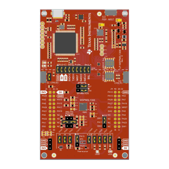
The following figure shows the LP-MSPM0L1306 LaunchPad development kit.
SLAU869D – OCTOBER 2022 – REVISED NOVEMBER 2023
Submit Document Feedback
ABSTRACT
™
Development Kit
is an easy-to-use evaluation module for the MSPM0L1306
LP-MSPM0L1306 LaunchPad Development Kit
Copyright © 2023 Texas Instruments Incorporated
MSPM0L1306 LaunchPad Development Kit (LP
‑ MSPM0L1306)
1
Advertisement
Table of Contents

Subscribe to Our Youtube Channel
Related Manuals for Texas Instruments MSPM0L1306


Summary of Contents for Texas Instruments MSPM0L1306
- Page 1 The board also features onboard buttons and LEDs for quick integration of a simple user interface, an onboard thermistor, light sensor, and RGB LED. The following figure shows the LP-MSPM0L1306 LaunchPad development kit. LP-MSPM0L1306 LaunchPad Development Kit ‑ MSPM0L1306) SLAU869D –...
-
Page 2: Table Of Contents
® are registered trademarks of Arm Limited. All trademarks are the property of their respective owners. ‑ MSPM0L1306) MSPM0L1306 LaunchPad Development Kit (LP SLAU869D – OCTOBER 2022 – REVISED NOVEMBER 2023 Submit Document Feedback Copyright © 2023 Texas Instruments Incorporated... -
Page 3: Getting Started
1.4 First Step Out-of-Box Experience An easy way to get started with the EVM is by using the preprogrammed out-of-box code. This code demonstrates some key features of the EVM and is meant to be used with the LP-MSPM0L1306 out-of-box demo GUI. -
Page 4: Next Steps: Looking Into The Provided Code
SysConfig for MSPM0 is another graphical tool that can be utilized to easily and quickly setup your MSPM0L1306 device, pins, and peripherals to fit your development needs. SysConfig is strongly encouraged to be used when starting any new project. With the XDS110 debug probe, debugging and downloading new code is simple. A connection between the EVM and a PC through the provided USB cable is all that is needed. -
Page 5: Hardware
MSPM0L1306 Alternate PA11 Selection Pullup voltage selection Light Sensor Thermistor RGB LED Figure 2-1. LP-MSPM0L1306 Overview ‑ MSPM0L1306) SLAU869D – OCTOBER 2022 – REVISED NOVEMBER 2023 MSPM0L1306 LaunchPad Development Kit (LP Submit Document Feedback Copyright © 2023 Texas Instruments Incorporated... -
Page 6: Jumper Map
UART Path Selection – BP – UART RX- XDS (1) short to (2) PA9 – XDS OFF to disconnect pin ‑ MSPM0L1306) MSPM0L1306 LaunchPad Development Kit (LP SLAU869D – OCTOBER 2022 – REVISED NOVEMBER 2023 Submit Document Feedback Copyright © 2023 Texas Instruments Incorporated... -
Page 7: Block Diagram
Four 16-bit general purpose timers • Internal 4- to 32-MHz oscillator with ±1% accuracy (SYSOSC) • 28 GPIOs ‑ MSPM0L1306) SLAU869D – OCTOBER 2022 – REVISED NOVEMBER 2023 MSPM0L1306 LaunchPad Development Kit (LP Submit Document Feedback Copyright © 2023 Texas Instruments Incorporated... - Page 8 2.3.2 XDS110-ET Onboard Debug Probe With EnergyTrace Technology To keep development easy and cost effective, the TI LaunchPad development kits integrate an onboard debug probe, which eliminates the need for expensive programmers. The MSPM0L1306 has the XDS110 debug probe (see Figure 2-4), which is a simple and low-cost debugger that supports all MSPM0 device derivatives.
- Page 9 Ground 5-V VBUS from USB 3.3-V rail, derived from VBUS in the XDS110-ET domain Backchannel UART: The target MSPM0L1306 receives data through this signal. The arrows indicate the direction of the RXD<< signal. Backchannel UART: The target MSPM0L1306 sends data through this signal. The arrows indicate the direction of the TXD>>...
- Page 10 The user can then open the port and begin communication from the host. On the target MSPM0L1306 side, the backchannel is connected to the UART0 module. The XDS110-ET has a configurable baud rate; therefore, the PC application configuring the baud rate to be the same as what is configured on the UART0 is important.
- Page 11 When using OPA and the passive network, be sure to check for conflicts with other pins on the LaunchPad EVM as pins are multiplexed with several functions. Figure 2-7. Thermistor Circuit ‑ MSPM0L1306) SLAU869D – OCTOBER 2022 – REVISED NOVEMBER 2023 MSPM0L1306 LaunchPad Development Kit (LP Submit Document Feedback Copyright © 2023 Texas Instruments Incorporated...
-
Page 12: Power
2.6 Measure Current Draw of the MSPM0 MCU To measure the current draw of the MSPM0L1306 MCU using a multimeter, use the 3V3 jumper on the J101 jumper isolation block. The current measured includes the target device, launchpad circuits, and any current drawn through the BoosterPack plug-in module headers. -
Page 13: Clocking
LaunchPad development kit is not compatible with all 40-pin BoosterPack plug-in modules due to the fact that the MSPM0L1306 device does not have enough pins to fill the standard. If the reseller or owner of the BoosterPack plug-in module does not explicitly indicate compatibility with the MSPM0L1306 LaunchPad development kit, then compare the schematic of the candidate BoosterPack plug-in module with the LaunchPad development kit to verify compatibility. -
Page 14: Resources
Learn more about CCS and download at http://www.ti.com/tool/ccstudio. Access the MSPM0 SDK and MSPM0L1306 code examples by using TI Resource Explorer within CCS. 4.2 MSPM0 SDK and TI Resource Explorer TI Resource Explorer is a tool integrated into CCS that allows the user to browse through available design resources. -
Page 15: Mspm0L1306 Mcu
MSPM0L1306 MCU. Every MSP derivative has a set of these code examples. When starting a new project or adding a new peripheral, these examples serve as a great starting point. -
Page 16: Schematics
Schematics www.ti.com 5 Schematics ‑ MSPM0L1306) MSPM0L1306 LaunchPad Development Kit (LP SLAU869D – OCTOBER 2022 – REVISED NOVEMBER 2023 Submit Document Feedback Copyright © 2023 Texas Instruments Incorporated... - Page 17 Schematics ‑ MSPM0L1306) SLAU869D – OCTOBER 2022 – REVISED NOVEMBER 2023 MSPM0L1306 LaunchPad Development Kit (LP Submit Document Feedback Copyright © 2023 Texas Instruments Incorporated...
- Page 18 Schematics www.ti.com ‑ MSPM0L1306) MSPM0L1306 LaunchPad Development Kit (LP SLAU869D – OCTOBER 2022 – REVISED NOVEMBER 2023 Submit Document Feedback Copyright © 2023 Texas Instruments Incorporated...
- Page 19 Schematics ‑ MSPM0L1306) SLAU869D – OCTOBER 2022 – REVISED NOVEMBER 2023 MSPM0L1306 LaunchPad Development Kit (LP Submit Document Feedback Copyright © 2023 Texas Instruments Incorporated...
- Page 20 Schematics www.ti.com ‑ MSPM0L1306) MSPM0L1306 LaunchPad Development Kit (LP SLAU869D – OCTOBER 2022 – REVISED NOVEMBER 2023 Submit Document Feedback Copyright © 2023 Texas Instruments Incorporated...
- Page 21 Schematics ‑ MSPM0L1306) SLAU869D – OCTOBER 2022 – REVISED NOVEMBER 2023 MSPM0L1306 LaunchPad Development Kit (LP Submit Document Feedback Copyright © 2023 Texas Instruments Incorporated...
-
Page 22: Revision History
Changes from Revision B (March 2023) to Revision C (March 2023) Page • Updated all images in Section 5 Schematics ....................‑ MSPM0L1306) MSPM0L1306 LaunchPad Development Kit (LP SLAU869D – OCTOBER 2022 – REVISED NOVEMBER 2023 Submit Document Feedback Copyright © 2023 Texas Instruments Incorporated... - Page 23 STANDARD TERMS FOR EVALUATION MODULES Delivery: TI delivers TI evaluation boards, kits, or modules, including any accompanying demonstration software, components, and/or documentation which may be provided together or separately (collectively, an “EVM” or “EVMs”) to the User (“User”) in accordance with the terms set forth herein.
- Page 24 www.ti.com Regulatory Notices: 3.1 United States 3.1.1 Notice applicable to EVMs not FCC-Approved: FCC NOTICE: This kit is designed to allow product developers to evaluate electronic components, circuitry, or software associated with the kit to determine whether to incorporate such items in a finished product and software developers to write software applications for use with the end product.
- Page 25 www.ti.com Concernant les EVMs avec antennes détachables Conformément à la réglementation d'Industrie Canada, le présent émetteur radio peut fonctionner avec une antenne d'un type et d'un gain maximal (ou inférieur) approuvé pour l'émetteur par Industrie Canada. Dans le but de réduire les risques de brouillage radioélectrique à...
- Page 26 www.ti.com EVM Use Restrictions and Warnings: 4.1 EVMS ARE NOT FOR USE IN FUNCTIONAL SAFETY AND/OR SAFETY CRITICAL EVALUATIONS, INCLUDING BUT NOT LIMITED TO EVALUATIONS OF LIFE SUPPORT APPLICATIONS. 4.2 User must read and apply the user guide and other available documentation provided by TI regarding the EVM prior to handling or using the EVM, including without limitation any warning or restriction notices.
- Page 27 Notwithstanding the foregoing, any judgment may be enforced in any United States or foreign court, and TI may seek injunctive relief in any United States or foreign court. Mailing Address: Texas Instruments, Post Office Box 655303, Dallas, Texas 75265 Copyright © 2023, Texas Instruments Incorporated...
- Page 28 TI products. TI’s provision of these resources does not expand or otherwise alter TI’s applicable warranties or warranty disclaimers for TI products. TI objects to and rejects any additional or different terms you may have proposed. IMPORTANT NOTICE Mailing Address: Texas Instruments, Post Office Box 655303, Dallas, Texas 75265 Copyright © 2023, Texas Instruments Incorporated...
Need help?
Do you have a question about the MSPM0L1306 and is the answer not in the manual?
Questions and answers